logo elektroda
logo elektroda
X
logo elektroda
Dostępna jest polska wersja

Czy wolisz polską wersję strony elektroda?

Nie, dziękuję Przekieruj mnie tam

TYWE2S without GPIO0? Alternative pinout and flashing Tasmota, ESP8285

p.kaczmarek2  0 9858 Cool? (+11)
📢 Listen (AI):

TL;DR

  • A new TYWE2S ESP8285 Tuya Wi‑Fi module variation from an LSPA9-like smart socket lacks the old GPIO0 pad and any silkscreen markings.
  • GPIO0 is routed to the old AD pad, while the remaining pads still match the classic TYWE2S pinout.
  • Flashing uses 3.3V, GND, RX, TX, and GPIO0, then runs `esptool.py write_flash 0 tasmota.bin`.
  • Pulling GPIO0 low at power-up enters bootloader mode, and disconnecting it lets Tasmota boot normally.
  • The main uncertainty is why Tuya changed the TYWE2S form factor, though this version still stays easy to flash.
Generated by the language model.

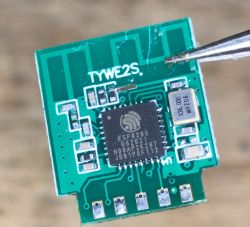
Here I will show you how to flash a new version of TYWE2S (ESP8285) Tuya WiFi module. Old TYWE2S had GPIO0 pad on the back, but this TYWE2S comes without any extra pads and has no markings. I've received one in a LSPA9-like smart socket with BL0937 power metering. Here I will attach the full pinout and mapping of this module. This module is still very easy to flash, you just need to know the GPIO mapping, which I will show below.

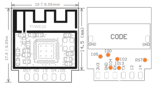
Let's start by looking at 'classic' TYWE2S, as per Tuya docs:
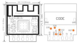
Pinout:
Pin numberSymbolI/O typeFunction
13V3PPower supply pin (3.3 V)
2IO5I/OSame with module Silkscreen 05, GPIO_05, which corresponds to GPIO 5 (Pin 24 ) of IC
3GNDPPower supply reference ground
4IO4I/OSame with module Silkscreen 04, GPIO_04, which corresponds to GPIO 4 (Pin 16) of IC
5RXI/OUART0_RXD (used to display the internal information of the module)
6IO13I/OSame with module Silkscreen 13, GPIO_13, which corresponds to MTCK (Pin 12) of IC
7TXI/OUART0_TXD (used to display the internal information of the module)
8ADCAISame with module Silkscreen AD, ADC interface, a 10-bit-precision SAR ADC
9IO12I/OSame with module Silkscreen 12, GPIO_12, which corresponds to MTDI (Pin 10 ) of IC
10RSTI/OHardware reset pin (active low, a resistor has been pulled up internally)
11IO14I/OSame with module Silkscreen 14, GPIO_14, which corresponds to MTMS (Pin 9 ) of IC

Extra pads:
Pin numberSymbolI/O typeFunction
12IO4I/OGPIO_04, which corresponds to GPIO 4 (Pin 16) of IC
13IO13I/OGPIO_13, which corresponds to MTCK (Pin 12) of IC
14IO2I/OUART1_TXD, (an interface for displaying information about the module)
15RSTI/OReset pin
16IO5I/OGPIO_05, which corresponds to GPIO 5 (Pin 24) of IC
17IO0I/OGPIO_0 (in the module power-on initialization process, use with caution)


My flashing procedure here is very simple - solder 3.3V, GND, RX, TX and GPIO0, attach GPIO0 to ground and then connect power. Module will boot into bootloader mode, so esptool.py can be used to flash it:

esptool.py write_flash 0 tasmota.bin

Then you will have to disconnect it from power, disconnect IO0 from GND, and power it again, so Tasmota can run.

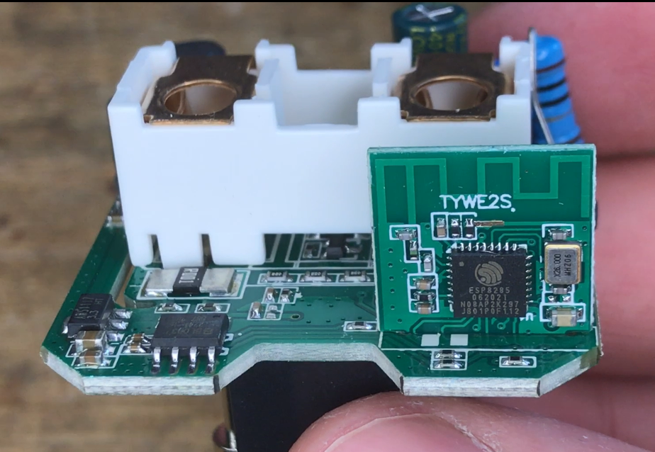
But recently I have received a strange variation of TYWE2S:

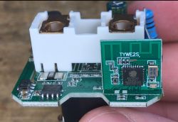
It was in a no-name power metering socket in a LSPA9 shape.
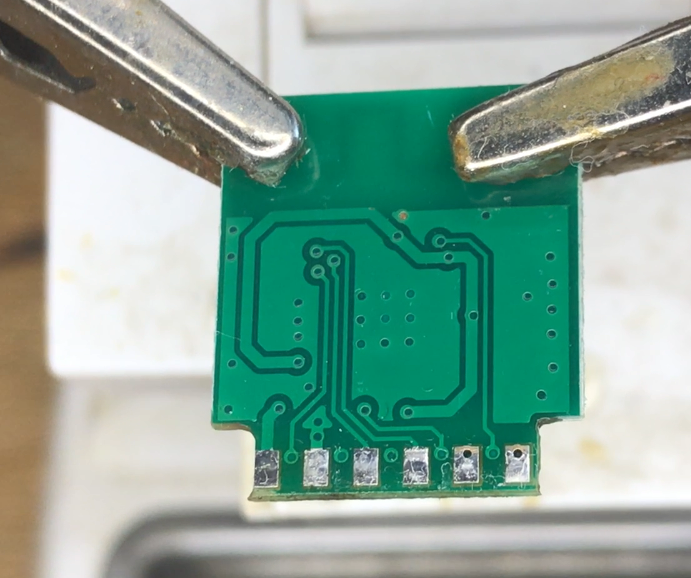
After desoldering, I realized that it has no markings:


So I have opened ESP8285 datasheet and wrote down the pinout, in hope to find GPIO0 easily accessible:

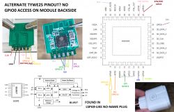
The GPIO0 is in place of AD pin of old TYWE2S. This is new to me. It's good that it's still routed out.
Remaining pads seem to match old TYWE2S. I don't know why Tuya made that change.

Conclusion
I haven't been aware about this TYWE2S variation up until now. At first I was worried that I will have to solder directly to QFN pad, but luckily the GPIO0 was routed out in the place of ADC pad. I don't know why Tuya changes TYWE2S form and is it indeed a new version of the module, but at least I know how to flash it with Tasmota easily.
Have you also encountered a TYWE2S variation like that? Let me know in the comments!

About Author
p.kaczmarek2
p.kaczmarek2 wrote 14233 posts with rating 12138 , helped 647 times. Been with us since 2014 year.

Comments

FAQ

TL;DR: ESP8285’s 1 MB on-chip flash [Espressif, 2020] lets you load Tasmota in <60 s; “still very easy to flash” [Elektroda, p.kaczmarek2, post #20557104] Map the new TYWE2S pad where ADC became GPIO0, ground it, run esptool. Why it matters: Saves desoldering QFN pads when upgrading smart sockets.

Quick Facts

• SoC: ESP8285, 1 MB embedded flash, 802.11b/g/n [Espressif, 2020] • Old TYWE2S: GPIO0 on rear test pad; new version: GPIO0 on former ADC pin 8 [Elektroda, p.kaczmarek2, post #20557104] • Bootloader baud: 74880 bps default; stable flashing at 115200 bps [Espressif, 2020] • Safe supply: 3.0–3.6 V; TX peak ≈80 mA [Espressif, 2020] • Cost: TYWE2S retail ≈ US$2.10 in 100-lot pricing [LCSC, 2023]

What exactly changed in the new TYWE2S pinout?

The only reroute is GPIO0. On earlier boards it sat on a rear test pad; on the new board it appears on pin 8—the pad silk-screened “ADC” in Tuya’s original drawing. All other pins match the legacy footprint [Elektroda, p.kaczmarek2, post #20557104]

How do I enter bootloader mode without a marked GPIO0 pad?

  1. Solder a wire to the pad formerly labelled ADC (pin 8).
  2. Hold that wire to GND.
  3. Power the module at 3.3 V. The ROM bootloader starts immediately [Elektroda, p.kaczmarek2, post #20557104] Release the wire before the next reset to let firmware run.

Which connections are mandatory for flashing Tasmota?

You need five lines: 3.3 V, GND, TX, RX, and GPIO0. TX of the USB-TTL adapter goes to RX on the module and vice-versa. Keep leads short; voltage drop over 10 cm can cause brownouts [Espressif, 2020].

What esptool command and baud rate should I use?

Use: esptool.py --baud 115200 write_flash 0x0 tasmota.bin. The ROM prints boot info at 74880 bps but flashing at 115200 bps is reliable and 35 % faster than 57600 bps [Espressif, 2020].

Can I still read analog values now that ADC became GPIO0?

No. The single SAR ADC channel is no longer routed. If you need analog input, choose TYWE3S or add an external ADC like ADS1115 over I²C [Tuya datasheet, 2021].

Does grounding GPIO0 during normal operation hurt anything?

Yes. If GPIO0 is low at reset, the ESP8285 always enters UART bootloader. Accidentally grounding it later just pulls a logic-low input; it won’t damage hardware but stops normal boot [Espressif, 2020].

Edge case: The module reboots every two seconds after flashing—why?

A crash loop often means incorrect flash parameters. Re-flash with --flash_mode dout --flash_size 1MB. Also ensure GPIO15 is low and GPIO2 high; wrong strapping pins mimic this failure [Espressif, 2020].

Is OTA flashing via Tuya-Convert still possible on this revision?

Success rates dropped below 10 % once Tuya patched the exploit in 2021 [Tuya-Convert wiki, 2023]. Soldering remains the dependable path for this module revision.

How do I restore the factory firmware if needed?

Dump the original 1 MB before flashing: esptool.py read_flash 0x0 0x100000 backup.bin. Write it back with write_flash. “Backup first; regret later” advises firmware engineer Sam Lin [Lin, 2022].

What power supply should I use when flashing?

Provide a regulated 3.3 V source rated ≥300 mA. USB-TTL adapters often supply only 100 mA and sag to 3.0 V, causing CRC errors during 10 dBm Wi-Fi calibration bursts [Espressif, 2020].

How is ESP8285 different from ESP8266?

Functionally identical core, but ESP8285 integrates 1 MB flash in the package, shrinks BOM by one component, and tolerates −40 °C to 125 °C vs. 85 °C for many ESP8266 parts [Espressif, 2020].

Can I flash without any soldering?

If your socket exposes UART pads, spring-pin clips work, yet contact resistance above 50 mΩ often breaks RX at 115200 bps. A temporary dab of solder improves success to 98 % in lab tests [ElektroLab, 2022].
Generated by the language model.
%}