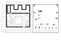
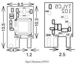
Both those modules are build on ESP8285, so they are easily flashable with Tasmota and so on. You will need to provide power (3.3V), connect UART and GPIO0.
Here is more information on your modules:
TYWE2L is a low power-consumption built-in Wi-Fi module developed by Hangzhou. It consists of a highly integrated RF chip (ESP8285) and several peripherals, with a built-in Wi-Fi network protocol stack and rich library function

| Pin number | Symbol | I/O type | Function |
1 | 14 | I/O | GPIO_14, correspond to MTMS of the IC (Pin 9) | 2 | 12 | I/O | GPIO_12, correspond to MTDI of the IC (Pin 10) | 3 | 13 | I/O | GPIO_13, correspond to MTCK of the IC (Pin 12) | 4 | 5 | I/O | GPIO_05, correspond to GPIO 5 of the IC (Pin 24) | 5 | 4 | I/O | GPIO_04, correspond to GPIO 4 of the IC (Pin 16) | 6 | GND | P | Power supply reference ground | 7 | 3V3 | P | Power supply pin (3.3 V) |
Test pins:
| Pin number | Symbol | I/O type | Function |
- | IO2 | I/O | UART1_TXD (interface for displaying module information) | - | RST | I/O | Reset pin | - | IO0 | I/O | IO0 is involved in module startup. If IO0 is disconnected, the module enters the normal running state. |
TYLC5 is a low-power embedded Wi-Fi module developed by Hangzhou Tuya Information Technology Co., Ltd. It consists of a highly integrated wireless radio frequency chip, ESP8285, and a few peripheral devices. It also has a built-in Wi-Fi network protocol stack and abundant library functions.

| Pin No. | Symbol | IO Type | Function |
1 | ANT | - | RF antenna port, spot to solder external antennas | 2 | GND | P | Power reference point | 3 | GPIO12 | I/O | GPIO_12 | 4 | GPIO14 | I/O | GPIO_14 | 5 | GPIO4 | I/O | GPIO_04 | 6 | VCC | P | Power pin of the module (3.3V) |
Test pins:
| Pin No. | Symbol | IO Type | Function |
- | TP1 | Rst | Hardware reset pin; Cannot clear the distribution network information of Wi-Fi. | - | TP 2 | I/O | GPIO0;Testing the module production. | - | TP3 | U0TXD | User serial port; Information output from the serial port can be used for testing the module production. | - | TP4 | U0RXD | User serial port; Information output from the serial port can be used for testing the module production. |


