logo elektroda
logo elektroda
X
logo elektroda

Teardown of 3 Generic Smart Switch Variants with ESP8265 10A TYWE2S Module & Flash Mode Guide

erlipan2001 2970 24
ADVERTISEMENT
  • Helpful post
    #1 20578046
    erlipan2001
    Level 6  
    I will condense 3 teardown into one post because they are very similar.

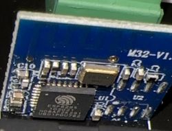
    They all use a variation of the TYWE2S module
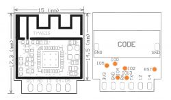
    Teardown of 3 Generic Smart Switch Variants with ESP8265 10A TYWE2S Module & Flash Mode Guide

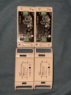
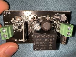
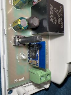
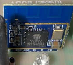
    First variant:
    Teardown of 3 Generic Smart Switch Variants with ESP8265 10A TYWE2S Module & Flash Mode Guide Teardown of 3 Generic Smart Switch Variants with ESP8265 10A TYWE2S Module & Flash Mode Guide Teardown of 3 Generic Smart Switch Variants with ESP8265 10A TYWE2S Module & Flash Mode Guide
    Teardown of 3 Generic Smart Switch Variants with ESP8265 10A TYWE2S Module & Flash Mode Guide
    Pinout:
    GPIO 4 BUTTON
    GPIO 5 RELAY
    GPIO 13 LED

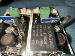
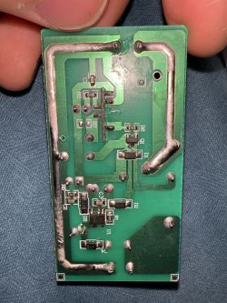
    Second variant:
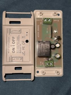
    Teardown of 3 Generic Smart Switch Variants with ESP8265 10A TYWE2S Module & Flash Mode Guide Teardown of 3 Generic Smart Switch Variants with ESP8265 10A TYWE2S Module & Flash Mode Guide Teardown of 3 Generic Smart Switch Variants with ESP8265 10A TYWE2S Module & Flash Mode Guide
    Teardown of 3 Generic Smart Switch Variants with ESP8265 10A TYWE2S Module & Flash Mode Guide
    Pinout:
    GPIO 4 LED
    GPIO 12 RELAY
    GPIO 13 BUTTON

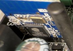
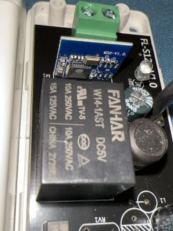
    Third variant:
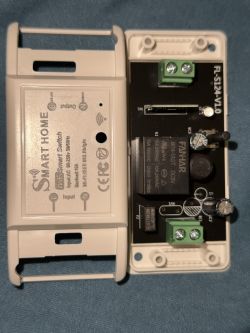
    Teardown of 3 Generic Smart Switch Variants with ESP8265 10A TYWE2S Module & Flash Mode Guide Teardown of 3 Generic Smart Switch Variants with ESP8265 10A TYWE2S Module & Flash Mode Guide Teardown of 3 Generic Smart Switch Variants with ESP8265 10A TYWE2S Module & Flash Mode Guide
    Teardown of 3 Generic Smart Switch Variants with ESP8265 10A TYWE2S Module & Flash Mode Guide
    Pinout: (Same as first)
    GPIO 4 BUTTON
    GPIO 5 RELAY
    GPIO 13 LED

    They all have a GPIO 0 pin on a test pad on the back of the module. I used a multimeter probe to put it in flash mode.
  • ADVERTISEMENT
  • #2 20578081
    p.kaczmarek2
    Moderator Smart Home
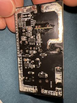
    It's a very nice comparison showing different manufacture approaches. Two of the models have single sided, cheap PCB, and third one has two sided one, but not populated.
    Teardown of 3 Generic Smart Switch Variants with ESP8265 10A TYWE2S Module & Flash Mode Guide
    It's not a good sight to see empty place for varistor and other components. I can also see a spot for SOIC8 chip, it was most likely used in RF-enabled version.

    Are you able to tell the Tasmota template for this devices, and also, which power supply ICs are they using?
    Helpful post? Buy me a coffee.
  • #3 20578088
    erlipan2001
    Level 6  
    I updated the post. Forgot to add some stuff.

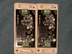
    First one is one sided so the front is quite busy. Other two are 2 sided.
  • #4 20578097
    p.kaczmarek2
    Moderator Smart Home
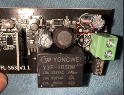
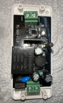
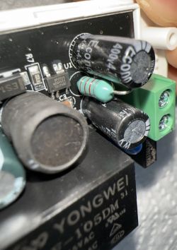
    That 0 ohm jumper in place of an inductor that was supposed to form a filter with capacitors is also not a good sign:
    Teardown of 3 Generic Smart Switch Variants with ESP8265 10A TYWE2S Module & Flash Mode Guide
    They usually put two electrolytic capacitors with an inductor between them, in that PCB, both inductor and one of capacitors are missing.

    I can also see power supply IC - BP2525, as usual.
    Helpful post? Buy me a coffee.
  • #5 20586703
    erlipan2001
    Level 6  
    Cracked open a new bunch of these and yep, some have the full circuit. From my basic understanding of electronics components some of the model I got have missing one electrolytic capacitor (Same value as the other black one), a ceramic capacitor and the resistor which I guess is current limiting (?).

    Teardown of 3 Generic Smart Switch Variants with ESP8265 10A TYWE2S Module & Flash Mode Guide Teardown of 3 Generic Smart Switch Variants with ESP8265 10A TYWE2S Module & Flash Mode Guide

    I should guess the cut down ones are fine to use? Worst case scenario I use them for stuff behind my UPS.

    Also considering that the versioning of the cut down is v1.1 I guess whoever made the circuit figured out that the filter was not strictly necessary so they bypassed it...
  • #6 20586823
    p.kaczmarek2
    Moderator Smart Home
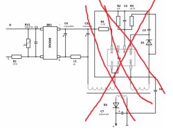
    This is how it was supposed to look like (except the crossed part, which is different on your power supply).
    Teardown of 3 Generic Smart Switch Variants with ESP8265 10A TYWE2S Module & Flash Mode Guide
    The blue element, which is missing from some boards, is a varistor, marked RV1.
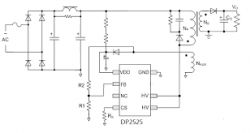
    Edit: maybe I was too eager to cross that part of schematic out, I can see you have BP2525 on the board, here's the BP2525 application:
    Teardown of 3 Generic Smart Switch Variants with ESP8265 10A TYWE2S Module & Flash Mode Guide
    so it's just like first schematic, just note that second one is missing the varistor (RV1, both on your PCB, and on the schematic)

    Well, to be honest, I saw people using such IoT low-price low-quality switches even without varistors for a very long time, so it's not that it will immediately blow up when you connect power... but in general, the thing that Chinese sellers do is not a good practice.

    @ElektrodaBot What is the varistor? How is varistor used in switching power supplies? How is it connected?
    Helpful post? Buy me a coffee.
  • #7 20586824
    ElektrodaBot
    AI OpenAI ChatGPT4
    p.kaczmarek2 wrote:
    What is the varistor? How is varistor used in switching power supplies? How is it connected?
    Hello user2529249!

    A varistor is a voltage-dependent resistor (VDR). It is a passive electronic component that exhibits a nonlinear relationship between its voltage and current. The main function of a varistor is to protect electronic circuits from voltage surges, such as lightning strikes or voltage spikes in the power supply.

    In switching power supplies, varistors are commonly used as a protective element to safeguard the circuitry from overvoltage conditions. They are connected in parallel to the input voltage source, usually across the AC mains input.

    When the voltage across the varistor is below its rated clamping voltage, it presents a high resistance and thus has little effect on the circuit. But when the voltage exceeds its rated clamping voltage, the varistor's resistance dramatically decreases, absorbing the sudden surge in voltage and diverting the excess current away from the sensitive components in the power supply.

    To better understand your specific application or requirements, it would be helpful if you could provide more details about the switching power supply you are working with, such as its specifications, intended use, and any specific concerns you may have regarding overvoltage protection.

    Feel free to ask any follow-up questions or provide more information. I'm here to help!
    You can call me in any topic by writing @ElektrodaBot. Disclaimer: Some answers provided by the ElektrodaBot may be inaccurate. Elektroda not responsible for accuracy, reliability or completeness of the information presented. All ElektrodaBot responses should be verified by the user. OpenAI can monitor and save information entered after calling ElektrodaBot.
  • ADVERTISEMENT
  • #8 20589195
    erlipan2001
    Level 6  
    >>20586823

    Well, I found out these two that have the non-hackable chip. I will put them aside and deal with them later.

    Maybe this non esp chip need extra filtering to be stable?

    Teardown of 3 Generic Smart Switch Variants with ESP8265 10A TYWE2S Module & Flash Mode Guide
  • #9 20589222
    p.kaczmarek2
    Moderator Smart Home
    Extra filtering/protection/etc should be always in smart relays, no matter what kind of WiFi chip is used.

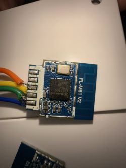
    So FL-M61 V2 is TR6260? Not good. I was looking into that TR6260 recently, but there is no flash tool at all.
    Helpful post? Buy me a coffee.
  • ADVERTISEMENT
  • #10 20589255
    erlipan2001
    Level 6  
    I total I found two variants of this chip.
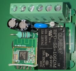
    This was the other one:
    Teardown of 3 Generic Smart Switch Variants with ESP8265 10A TYWE2S Module & Flash Mode Guide

    Looks very similar. Luckily for me I bought so many of them that I won't have to for years.
  • #11 20589262
    p.kaczmarek2
    Moderator Smart Home
    XY-WE2S-A V1.1.. so many strange names...

    But you can replace it with ESP-02S.
    Helpful post? Buy me a coffee.
  • #12 20589266
    erlipan2001
    Level 6  
    I know but for some reason buying a replacement module costs more than what I paid for the whole thing. (I paid 1.79$ for the switch vs 4$ for the ESP-02S).

    So it makes more economical sense just to trash it and buy again considering that only 1 out of 20 had this chip.
  • Helpful post
    #13 21400367
    divadiow
    Level 34  
    @erlipan2001 there is now a backup and flash tool and an OpenTR6260 firmware that can be flashed to these modules.

    If you're able to follow the new guide to backup the existing firmware, that would be very useful.

    https://www.elektroda.com/rtvforum/topic4093752.html

    @morgan_flint is battling with an XY-WE2S-A V1.1 right now to make a backup.
  • #14 21402294
    morgan_flint
    Level 14  
    >>21400367
    divadiow wrote:
    @morgan_flint is battling with an XY-WE2S-A V1.1 right now to make a backup.

    Done!!
    Check my PM to see if it's correct and I'll post afterwards the relevant info
  • #15 21402346
    p.kaczmarek2
    Moderator Smart Home
    That TR6260 device is Tuya? I wonder if it has a Tuya JSON in flash as well?
    Helpful post? Buy me a coffee.
  • #16 21402359
    divadiow
    Level 34  
    p.kaczmarek2 wrote:
    I wonder if it has a Tuya JSON in flash as well?


    I'm hoping so. This is partly why I've been so excited about getting my hands on a Tuya TR6260!
  • #17 21402508
    morgan_flint
    Level 14  
    >>21402346 Yes, I could control it with Tuya Smart App and also with Smart Life.
    @divadiow now has the full dump, once he checks it's alright, I'll post it here or, maybe better, in the flashing guide, you'll tell me where it should go
  • #18 21402580
    divadiow
    Level 34  
    great work!

    I have flashed the file to HLK-M20 and yes it does boot but it loops like this:

    Code: Text
    Log in, to see the code


    however I carve the file up it does the same - app partition flashed only but with Skylab-supplied other bits, your AP creds broadcasting, tuya_mdev_test1 AP broadcasting, pulling low all the GPIOs I have available to me in the hope one is the button and it'll factory reset etc etc

    It does for a brief period broadcast
    Screenshot showing a Wi-Fi network named SmartLife-7C96.

    but not long enough to join for more than a second

    if you're still up for playing, does it boot fully as a removed module for you? Does it boot fully soldered back into the device? When it is back in device are you able to get it into pairing mode with the usual button push down for a few seconds? If yes, please take a backup with it in pairing mode.

    Added after 1 [hours] 20 [minutes]:

    what looks to be firmware key and product key in your binary

    Code: Text
    Log in, to see the code

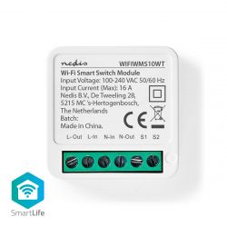
    comes back as WIFIWMS10WT - schema ID: 000004f9cj - Breaker (tdq) from Tuya API

    which appears to correlate nicely with the name of file you sent NedisWIFIWMS10WT_0x100000.bin
    https://nedis.co.uk/en-gb/product/smart-home/...inal-connection-app-available-for-android-ios

    Nedis WIFIWMS10WT smart switch module with input voltage and current information and connectors.
  • #19 21403049
    morgan_flint
    Level 14  
    divadiow wrote:
    if you're still up for playing, does it boot fully as a removed module for you?

    Yes, all the tests I commented on in private messages were done like this, To simulate switching the external switch to put it in pairing mode I just connected momentarily the corresponding GPIO to GND six times.
    divadiow wrote:
    Does it boot fully soldered back into the device?

    No, I haven't resoldered to the device it yet, as I think it's better for testing. I have no doubt it will boot when resoldered, as I didn't make any changes yet.
    divadiow wrote:
    When it is back in device are you able to get it into pairing mode with the usual button push down for a few seconds?

    I can simulate pressing the push button in the same way but I didn't do it before because the manual didn't mention it. I'll try now.
    divadiow wrote:
    which appears to correlate nicely with the name of file you sent NedisWIFIWMS10WT_0x100000.bin

    Yes, that's exactly the device. Inside, it's the same as the one posted by @erlipan2001 here
  • #20 21403132
    divadiow
    Level 34  
    Ah ok. Sure.
    I was wondering maybe if your device is pulling one of the GPIOs high and that's what is needed, but I guess not if you say it boots with the module desoldered.

    Added after 2 [minutes]:

    Or maybe it's my module in ESP adaptor. I could try flash to another TR6260 or remove module and connect up naked

    Added after 37 [seconds]:

    @insmod do you full HLK-M20 dev board?
  • ADVERTISEMENT
  • #22 21403163
    morgan_flint
    Level 14  
    divadiow wrote:
    I was wondering maybe if your device is pulling one of the GPIOs high and that's what is needed, but I guess not if you say it boots with the module desoldered.

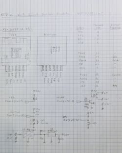
    It's pulling high pins 15 and 17, but probably not needed, as it boots unsoldered from the device. I've just finished drawing the schematic:

    Diagram of a Wi-Fi Smart Switch circuit drawn on graph paper.

    For reading and flashing, the following pads at the bottom side are used: TXD and RXD to USB to serial adapter's RXD and TXD, respectively, BT0 to GND and Vcc to 3.3V (my USB to serial adapter is modified for 3.3V levels at TXD and RXD).

    I'm also attaching the full dump (the one I sent to @divadiow with the WiFi SSID and password removed by him, still pending to try to reset it with a long press of the key).
  • #23 21403171
    divadiow
    Level 34  
    nice. maybe it's just my setup. I'll change things up and try more

    Added after 1 [minutes]:

    interestingly I do see these sometimes

    Code: Text
    Log in, to see the code
  • #24 21403194
    morgan_flint
    Level 14  
    divadiow wrote:
    I have flashed the file to HLK-M20 and yes it does boot but it loops like this:

    Could it be because it doesn't connect to the WiFi?
    Have you tried overwritting my SSID-password with yours?
  • Helpful post
    #25 21403406
    divadiow
    Level 34  
    I am further and almost had it paired. Removed the ESP adaptor from equation and used ext 3.3v PSU. It also joins an AP with your creds specified. I just need to get it to reset.

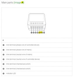
    Instructions excerpt:


    If the indicator LED A7 is not blinking
    a.
    Switch off the power group again.
    b.
    Check if all wires are connected well.
    c.
    Switch the power group back on.
    If the indicator LED A7 is blinking continue with step 5..
    If not, continue with step d..
    d.
    Switch the mechanical switch on and off 6 times to reset the product.
    If you have no mechanical switch connected to the product, bridge the wire terminal A5 to the wire terminal A6 with a wire 6 times to reset the product.


    manual

    Diagram showing the main parts of a device with labeled wire terminals and an indicator LED.

    I just need to work out if I can achieve that with just the module

    Added after 1 [minutes]:

    new boot log as I fiddle with GPIOs and resets

    Code: Text
    Log in, to see the code


    Added after 4 [hours] 50 [minutes]:

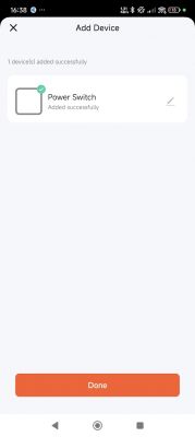
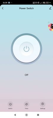
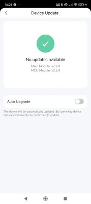
    OK. I paired it twice. Don't ask me how I got it into the right mode to stay in AP mode long enough. To pair you must use the slow-blink manual pairing mode in the app, if you ever get it to broadcast SmartLife AP long enough.

    Here's another part of the boot log, you can see the product and firmware keys I posted earlier

    Code: Text
    Log in, to see the code


    App screen confirming the addition of the Power Switch device. App screen showing a power switch that is turned off. Device update screen showing no updates available.

    reset firmware (containing creds for AP SSID test password 1234abcd) will land here https://github.com/openshwprojects/FlashDumps/tree/main/IoT/TR6260

    Tuya_Nedis_WMS10WT_Breaker_(schemaID-000004f9cj)_shoyx238jhhnxbef_2.2.4.bin

Topic summary

The discussion focuses on the teardown of three generic smart switch variants utilizing the TYWE2S module, highlighting their similarities and differences in design and components. The first variant features a single-sided PCB, while the other two are double-sided. Concerns are raised about missing components, such as varistors and capacitors, which are critical for circuit stability and protection. The BP2525 power supply IC is identified in the designs. Users discuss the implications of these omissions on device reliability and safety, particularly regarding voltage surges. Additionally, some variants contain non-hackable chips, prompting considerations for extra filtering and the economic viability of replacing modules versus purchasing new switches.
Summary generated by the language model.
ADVERTISEMENT