logo elektroda
logo elektroda
X
logo elektroda

[BK7231N/CBU] WiFi Modemix MOD003 Dual Light Controller

p.kaczmarek2  0 3438 Cool? (+2)
📢 Listen (AI voice):

TL;DR

  • WiFi Modemix MOD003 BK7231N/CBU dual light controller offers two relays and two external switch inputs in a 46x46x18mm housing.
  • Inside, a CBU daughterboard carries the pairing LED and button, while the main board uses an 1117 3.3V LDO and KP15051SP transformerless converter controller.
  • Flashing OpenBeken needs only RX, TX, GND and 3.3V, and the BK7231GUIFlashTool uses the CSN test point to enter boot mode.
  • The pin map assigns P7, P9, P17, P8, P24 and P26 to the Wi‑Fi LED, both relays, the pairing button and both switches.
  • The firmware change worked and enabled local Home Assistant control, but the unit is about PLN 70, lacks mounting accessories, and needs PowerSave 1 to protect the non-isolated supply.
AI summary based on the discussion. May contain errors.

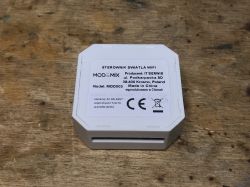
It's time for a review and release from the cloud of another small module for the box, this time offering control of two relays via WiFi, additionally allowing you to connect two switches to them. The module described here was bought in our country this time, so there was no waiting for shipping, but it cost a bit more than the gadgets imported straight from China, although it was not as expensive as in the case of other products, including the recently described RR400W , which for PLN 70 offers only one relay and without the possibility of connecting an external button (unless we load OpenBeken, then you can configure the pins at will and you can connect an additional button / sensor that was not planned by the manufacturer).
The topic will only cover the interior and the firmware change. As usual - I skip the Tuya application and immediately look inside.

Buying a kit
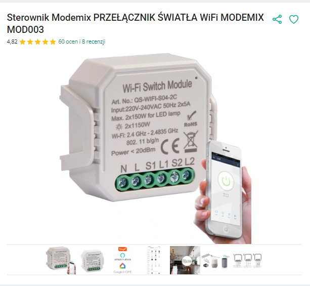
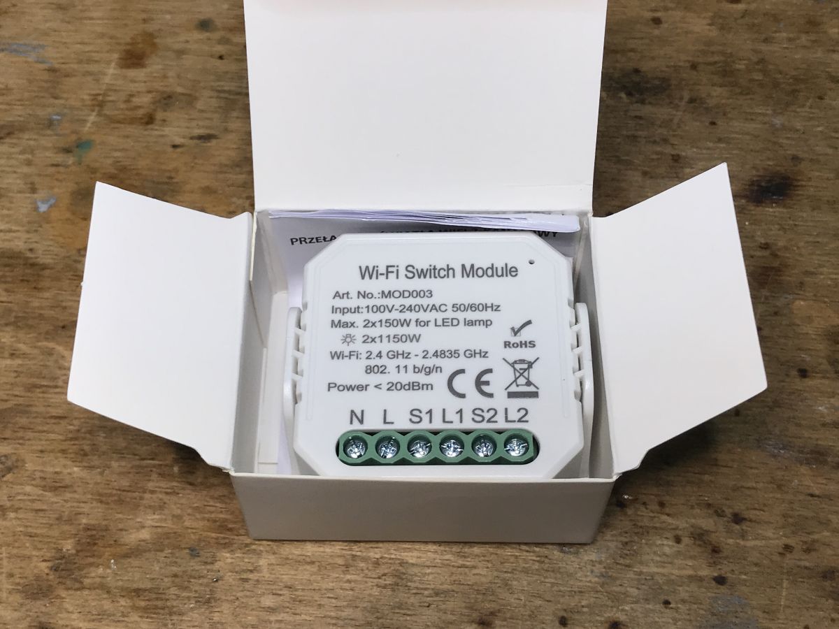
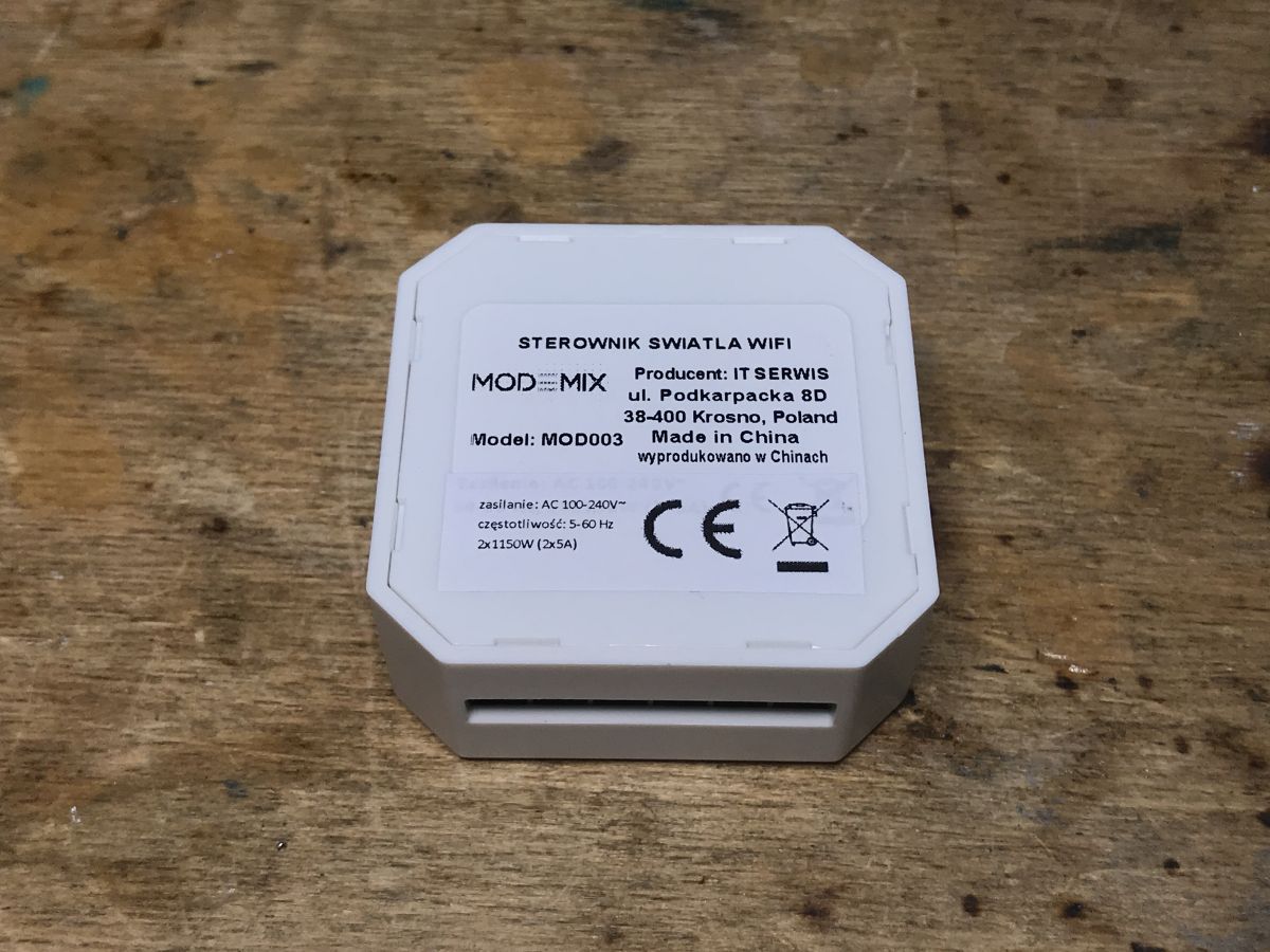
One of my readers gave me the set ( Thank you very much! ) so that I can change the firmware for it. As far as I know, such a driver can be purchased in several places on the Polish Internet, e.g. on a popular auction site. It is quite expensive, all PLN 70, but at least it can handle two lines - it has two relays inside.
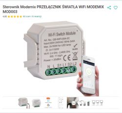
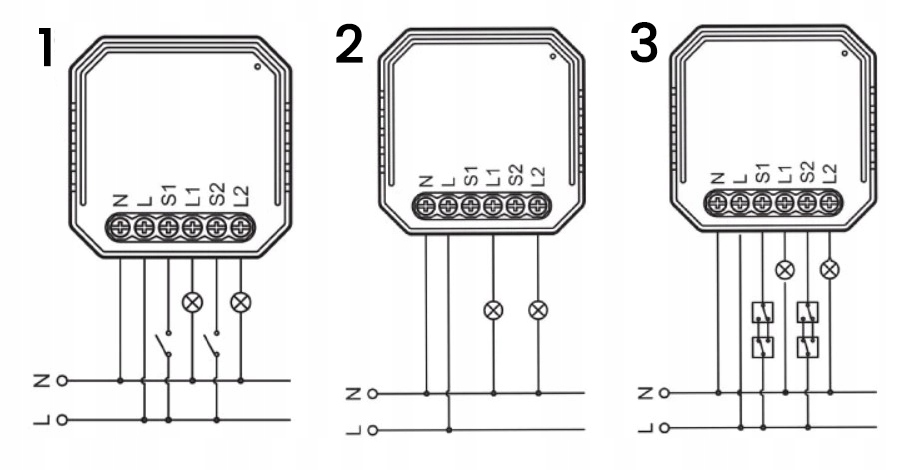
assembly diagram:

Dimensions: 46x46x18mm
Before buying, check whether it fits our box and whether we will have a way to lead wires to it.

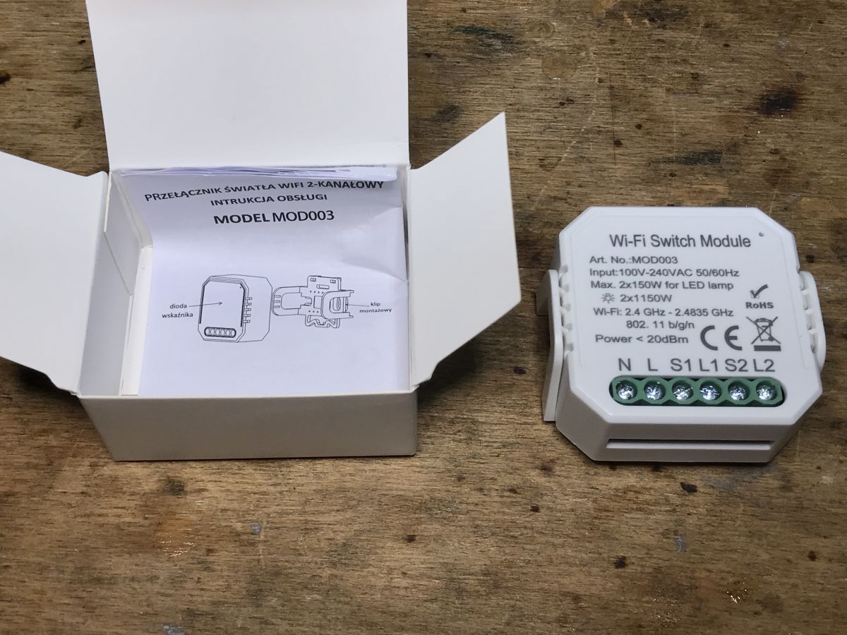
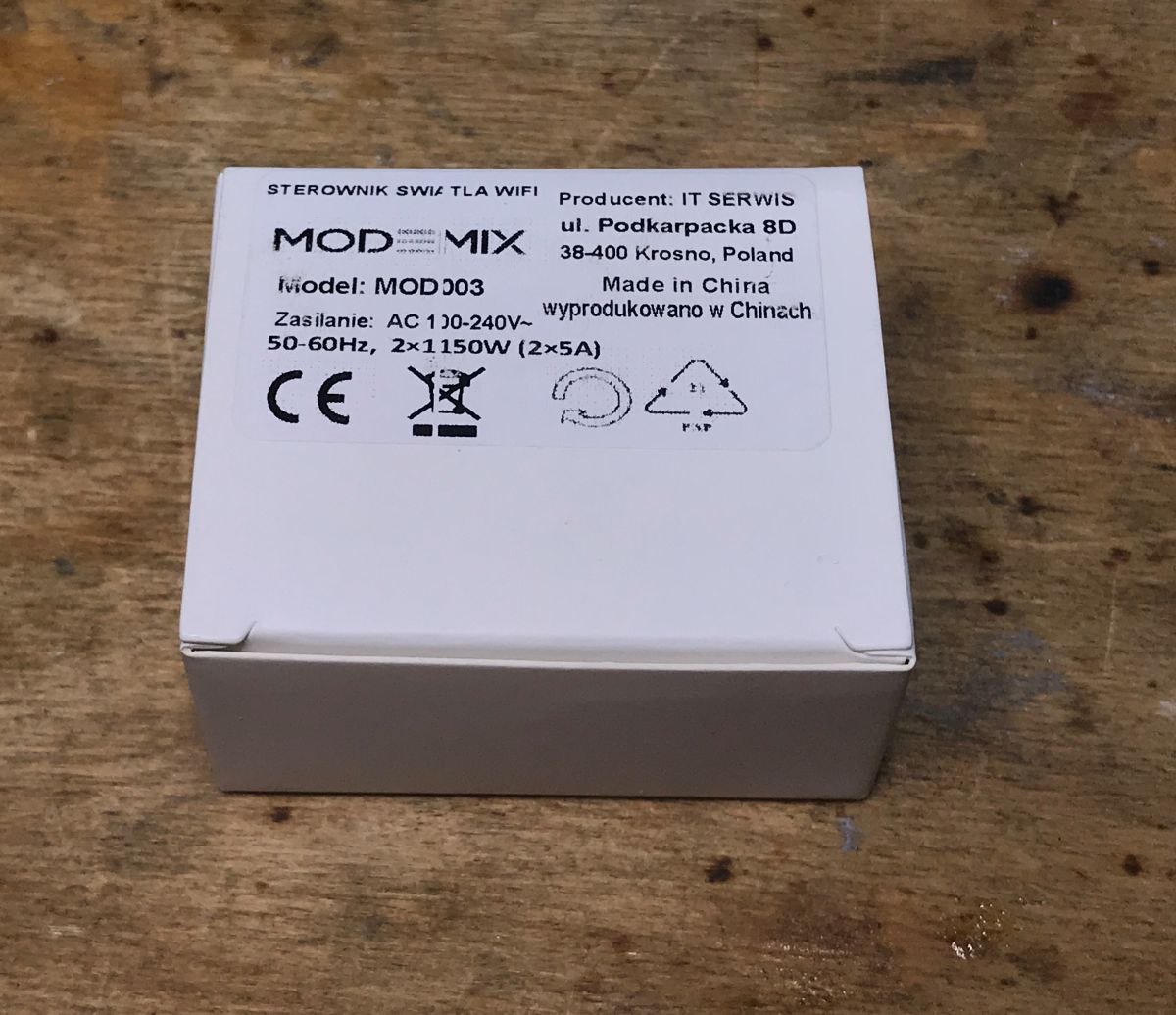
Kit contents
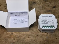
This time the set is quite poor. We don't even get screws or even a strip of double-sided tape for fixing. Pity.
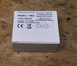
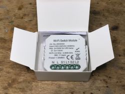
Enough of the introduction, let's take a look inside.

MOD003 interior
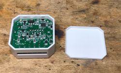
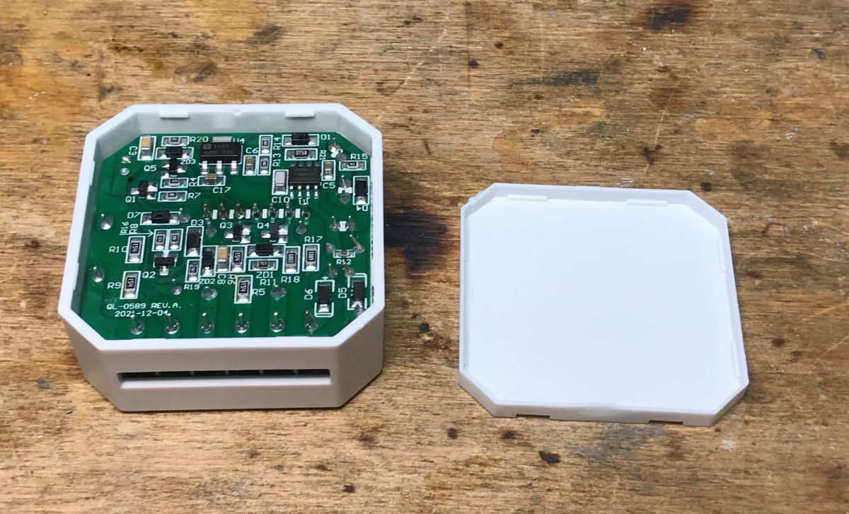
As usual, it is enough to pry the casing. No screws.
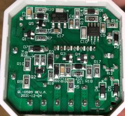
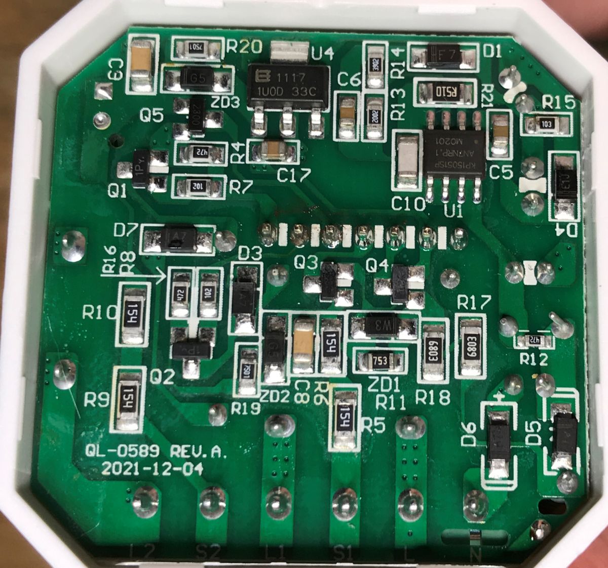
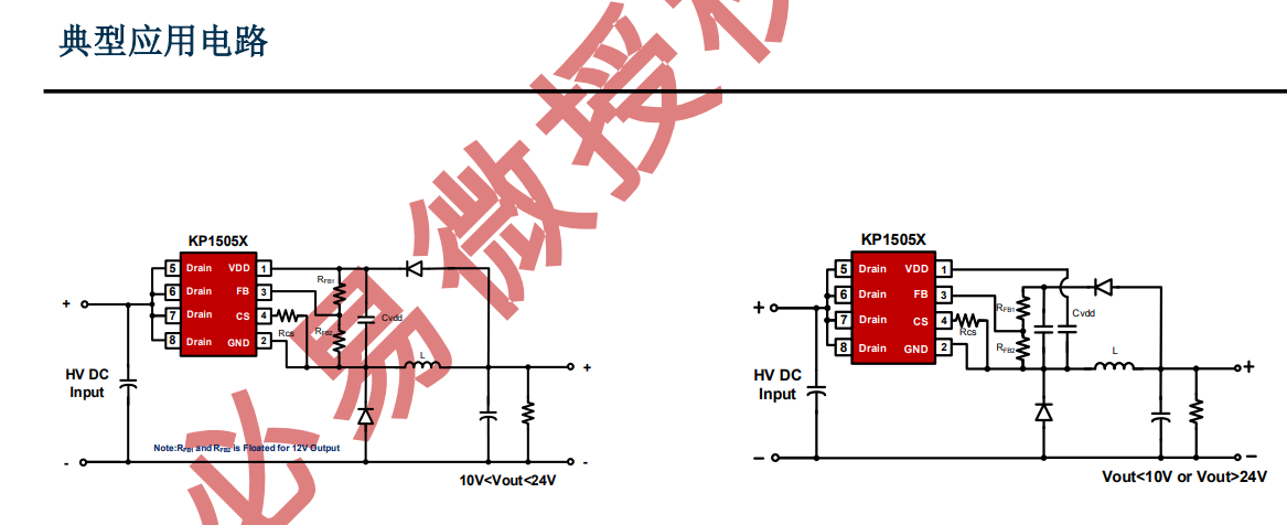
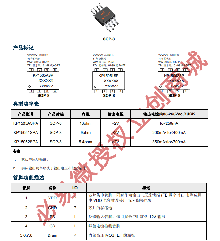
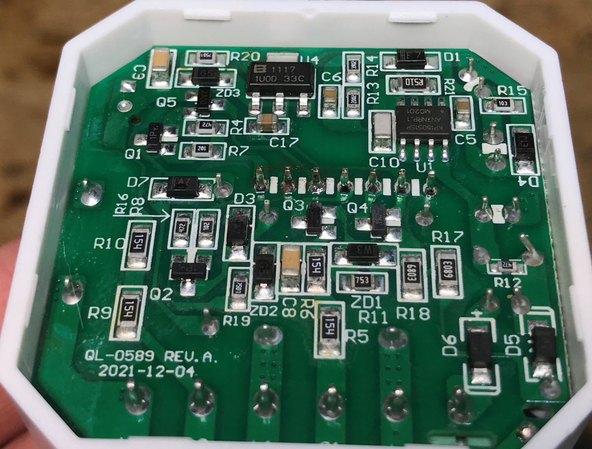
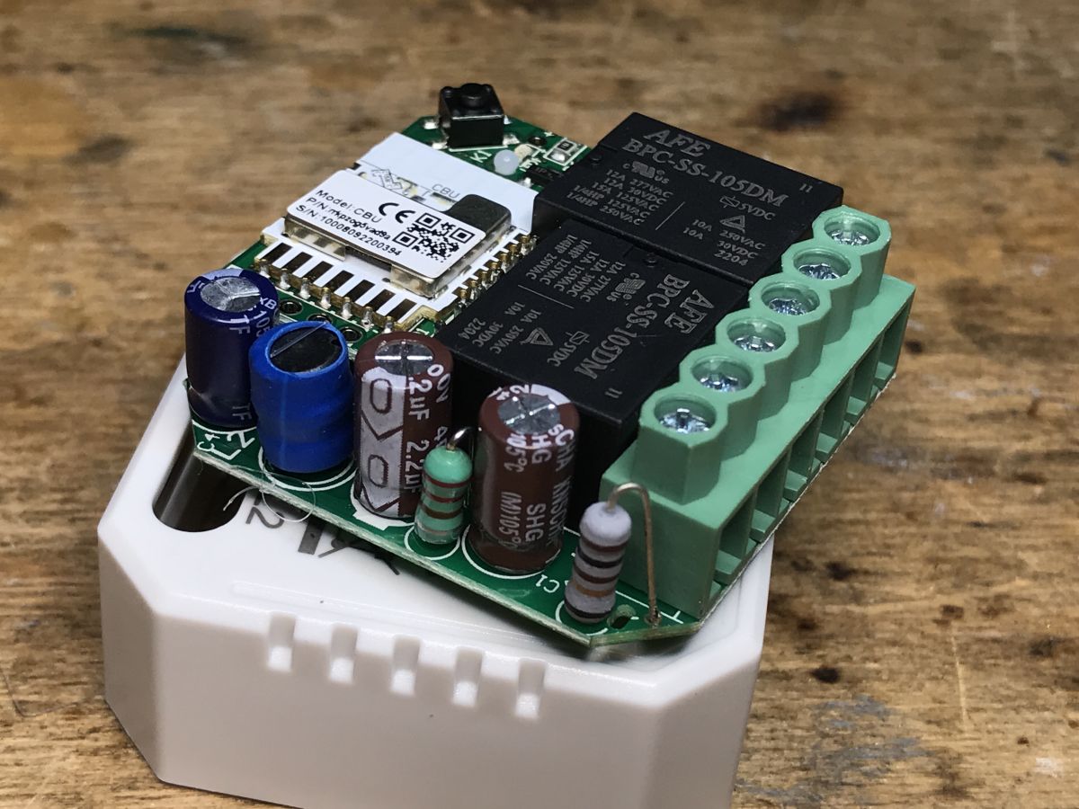
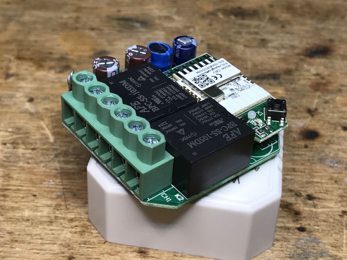
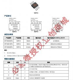
Inside, you can see the LDO 1117 3.3V regulator and the KP15051SP transformerless converter controller.
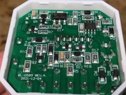
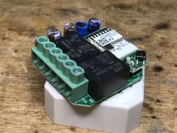
Now you need to pull out the PCB. This time it comes out quite hard, it looks like there is a plate on the plate and something hooks.
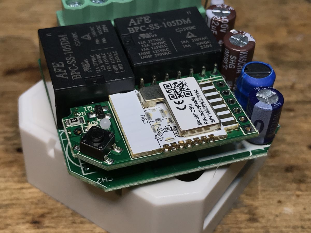
What is it that hooks?
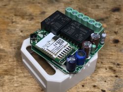
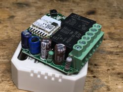
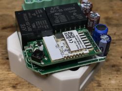
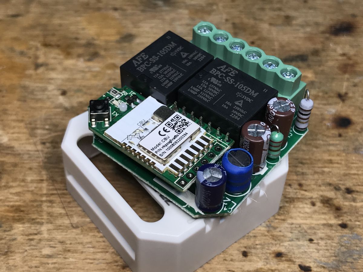
The extra PCB with the CBU module hooked up. Interestingly, the pairing LED and the pairing button are on this additional board. Goldpins, ground, power supply and inputs for two buttons and outputs for two relays go from this board.
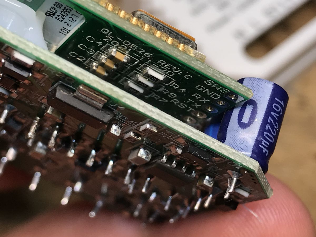
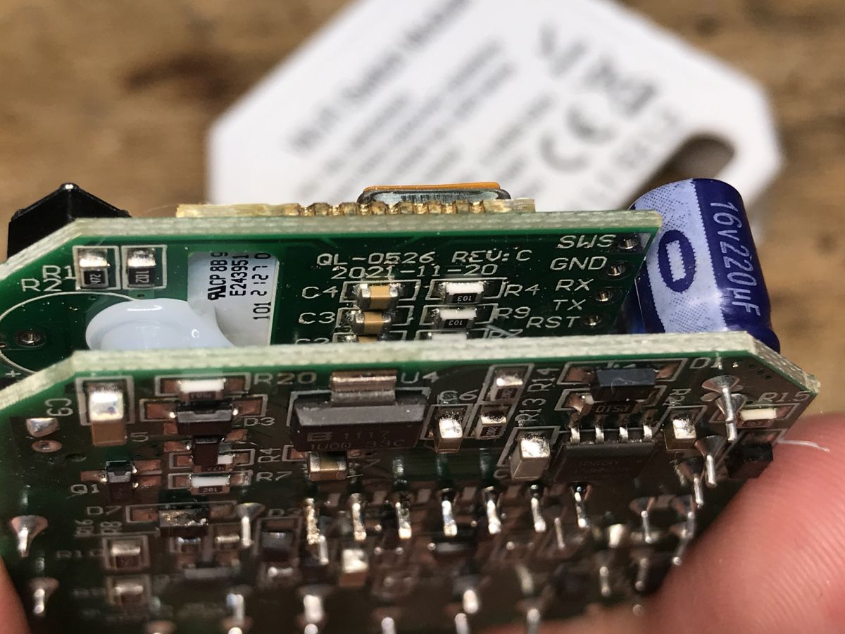
Looking under this PCB, we can see the signal markings:
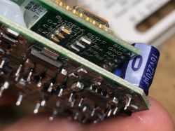
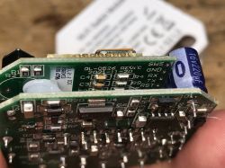
The description of the CBU is also on the web...

MOD003 programming
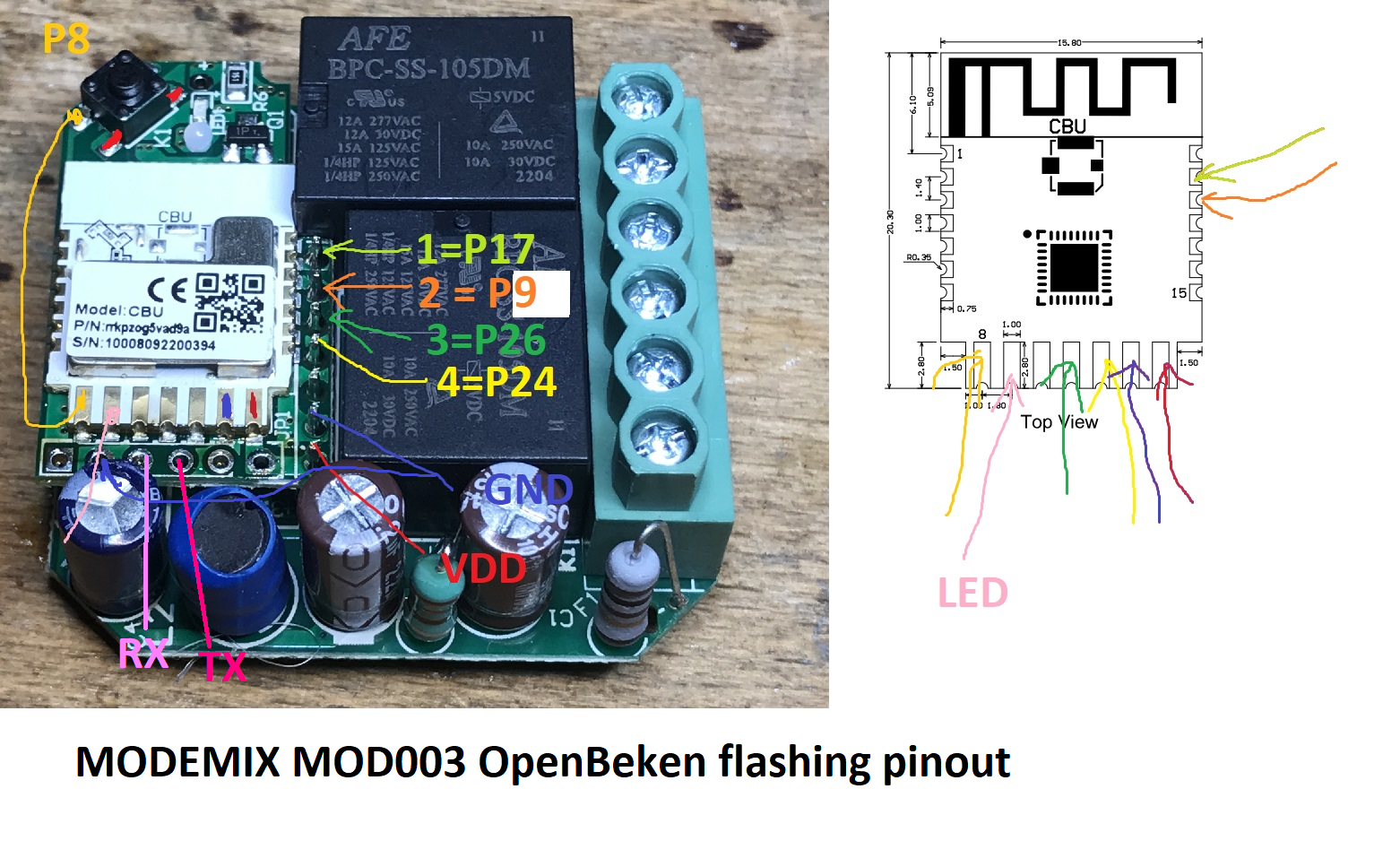
Here is the full list of connections required for programming and hardware configuration after OpenBeken has been uploaded:
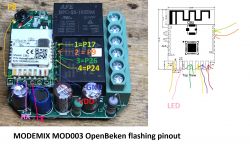
CBU Pinout:
Quote:

pin number Symbol I/O type functions
1 P14 I/O Common GPIO, which can be reused as SPI_SCK (Correspond to Pin 11 of the IC)
2 P16 I/O Common GPIO, which can be reused as SPI_MOSI (Correspond to Pin 12 of the IC)
3 P20 I/O Common GPIO (Correspond to Pin 20 of the IC)
4 P22 I/O Common GPIO (Correspond to Pin 18 of the IC)
5 ADC I/O ADC, which corresponds to P23 on the internal IC (Correspond to Pin 17 of the IC)
6 RX2 I/O UART_RX2, which corresponds to P1 on the internal IC. (Correspond to Pin 28 of the IC)
7 TX2 I/O UART_TX2, which is used for outputting logs and corresponds to P0 of the internal IC (Correspond to Pin 29 of the IC)
8 P8 I/O Support hardware PWM (Correspond to Pin 24 of the IC)
9 P7 I/O Support hardware PWM (Correspond to Pin 23 of the IC)
10 P6 I/O Support hardware PWM (Correspond to Pin 22 of the IC)
11 P26 I/O Support hardware PWM (Correspond to Pin 15 of the IC)
12 P24 I/O Support hardware PWM (Correspond to Pin 16 of the IC)
13 GND P Power supply reference ground
14 3V3 P Power supply 3V3
15 TX1 I/O UART_TX1, which is used for transmitting user data and corresponds to Pin 27 of the IC. For the MCU solution, please refer to CBx Module.
16 RX1 I/O UART_RX1, which is used for receiving user data and corresponds to Pin 26 of the IC. For the MCU solution, please refer to CBx Module.
17 P28 I/O Common GPIO (Correspond to Pin 10 of the IC)
18 CEN I/O Reset pin, low active (internally pulled high), compatible with other modules (Correspond to Pin 21 of the IC)
19 P9 I/O Common GPIO (Correspond to Pin 25 of the IC)
20 P17 I/O Common GPIO, which can be reused as SPI_MISO (Correspond to Pin 14 of the IC)
21 P15 I/O Common GPIO, which can be reused as SPI_CS (Correspond to Pin 13 of the IC)
test point CSN I/O mode selection pin. If it is connected to the ground before being powered on, enter the firmware test mode. If it is not connected or connected to VCC before being powered on, enter the firmware application mode. Correspond to Pin 19 on the internal IC.


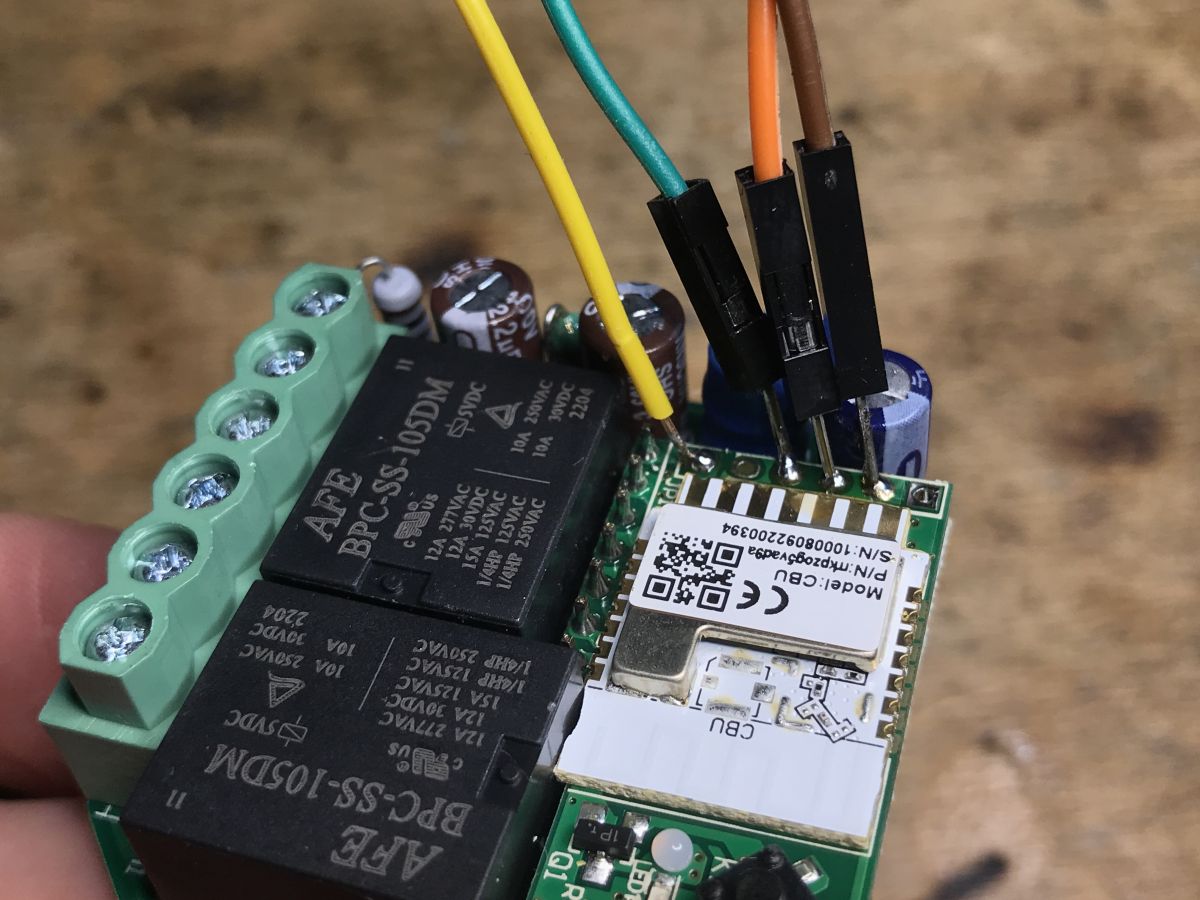
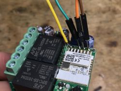
Here are the soldered wires - RX, TX, GND and 3.3V:
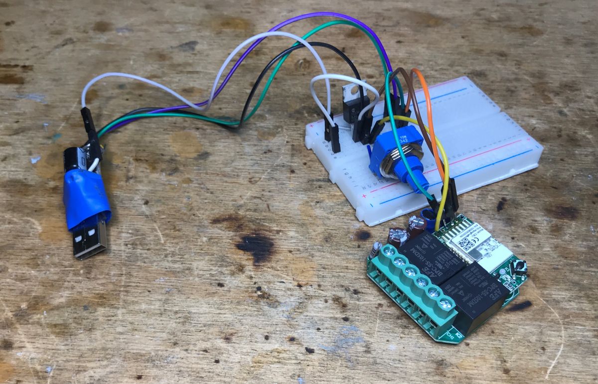
Ready circuit with LDO 3.3V and USB to TTL converter:
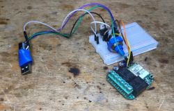
We program with this:
https://github.com/openshwprojects/BK7231GUIFlashTool
It is important for this device to first disconnect 5V from the LDO, then connect the USB to TTL converter to the computer, then start the flashing procedure (Getting Bus), and then connect the power supply (then the Getting bus will be successful and the proper reading / uploading of the firmware will start) .
In summary, the pins are:
- P7 - WiFi LED
- P9 - Relay 1
- P17 - Relay 2
- P8 - pairing button (from the housing)
- P24 - Switch 1
- P26 - Switch 2
Same with OpenBeken JSON format:
Code: JSON
Log in, to see the code

If we want to connect a bistable button, then in OBK we use the role of TglChannelOnToggle, and if a momentary button, then Button.
OpenBeken Documentation:
https://github.com/openshwprojects/OpenBK7231T_App/blob/main/docs/README.md
Repository:
https://github.com/openshwprojects/OpenBK7231T_App

Summary
All in all, it wasn't that difficult, it was enough to solder 4 wires and the firmware change was successful. The module is quite nice, and the RX and TX outputs can then be used as regular GPIOs and, for example, connect DHT11 or SHT30 and additionally configure it in OpenBeken to send results to Home Assistant. It's just a few clicks in the web panel of the new firmware. Of course, you have to be careful, because the power supply on board does not provide galvanic separation, but this is the norm for this type of product. The possibilities after changing the firmware are really great.
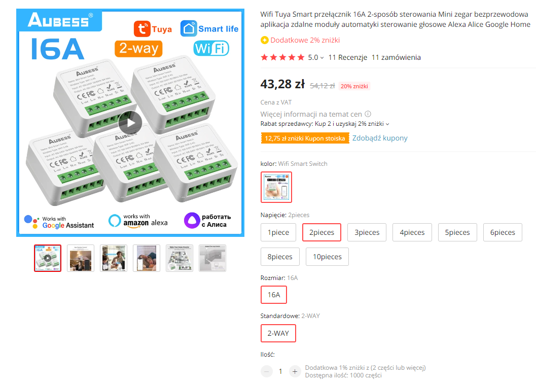
There is also the issue of price - this time it was not as bad as in the case RR400W , but it's still hard not to notice that the classic Aubess Smart Switch directly from China can be up to two times cheaper, screenshot from the auction in the spoiler:
Spoiler:


So I don't know if I can recommend a product from the theme. I also tested the cheapest Aubess from Aliexpress and I know that it works well with OpenBeken, but one thing should be remembered: after changing the firmware, we must make sure that we use the option PowerSave , i.e. from dynamic energy saving, otherwise the budget power supply from the deck will simply fail over time and you will have to replace the capacitors, as I described here:
How to fix a smart device that crickets, squeaks and makes strange noises?
In OpenBeken, just type PowerSave 1 in Startup Command and this will activate low power mode after every reboot.
That's it for now, thank you to a friend from outside the forum for giving me another product to review . After uploading the firmware, the product returned to the donor so that he could enjoy the ability to control the light without the Tuya cloud, all 100% locally, from the Home Assistant level.

About Author
p.kaczmarek2
p.kaczmarek2 wrote 14717 posts with rating 12794 , helped 659 times. Been with us since 2014 year.

Comments

FAQ

TL;DR: MOD003 has 2 relays, and the practical expert verdict is: "It wasn’t that difficult." This FAQ helps Home Assistant users flash OpenBeken on the BK7231N/CBU Modemix MOD003 for fully local light control without the Tuya cloud. [#20572374]

Why it matters: The Modemix MOD003 can become a local, two-channel WiFi light controller after a 4-wire UART flash, but its non-isolated power supply demands careful handling.

Alternative Channels Approx. price in thread External switch support Local OpenBeken control
Modemix MOD003 2 relays 70 PLN 2 switch inputs Yes
RR400W 1 relay 70 PLN Not manufacturer-planned Yes, after pin configuration
Aubess Smart Switch Typical 1 relay Up to 2× cheaper than MOD003 Not detailed Yes

Key insight: The core MOD003 setup is simple: flash BK7231N over UART, map six GPIO roles, then use PowerSave 1 to reduce stress on budget power supplies.

Quick Facts

  • MOD003 dimensions are 46x46x18 mm, so box depth and wire routing must be checked before purchase. [#20572374]
  • The module cost cited in the thread is 70 PLN and includes 2 relays, but the kit lacks screws and double-sided tape. [#20572374]
  • Programming uses 4 soldered connections: RX, TX, GND and 3.3 V, with an external USB-to-TTL adapter. [#20572374]
  • Internal power hardware includes an LDO 1117 3.3 V regulator and a KP15051SP transformerless converter controller. [#20572374]
  • OpenBeken pin roles include P7 WiFi LED, P9 Relay 1, P17 Relay 2, P24 Switch 1 and P26 Switch 2. [#20572374]

How do you flash OpenBeken onto the Modemix MOD003 dual relay light controller with a BK7231N CBU module?

Flash OpenBeken by soldering UART wires and using BK7231GUIFlashTool on the BK7231N CBU module.
  1. Solder RX, TX, GND and 3.3 V to the CBU programming points.
  2. Disconnect 5 V from the LDO, connect USB-to-TTL, then start “Getting Bus”.
  3. Apply power only after “Getting Bus” starts, then read or upload firmware.
The author reports the firmware change succeeded after soldering only 4 wires. [#20572374]

What GPIO pin configuration should be used in OpenBeken for the Modemix MOD003 2-gang relay module?

Use P7 for the WiFi LED, P9 and P17 for relays, and P24 and P26 for wall switches. Configure P8 as the housing pairing button. In OpenBeken JSON, the roles are: P7 WifiLED_n, P8 Btn_Tgl_All, P9 Rel;1, P17 Rel;2, P24 TglChanOnTgl;1, and P26 TglChanOnTgl;2. This maps both MOD003 relay channels and both external switch inputs. [#20572374]

What is the CBU module used in BK7231N-based Tuya smart switches?

CBU is the WiFi control board inside this MOD003, built around the BK7231N chip. "CBU is a Tuya-style embedded WiFi module that exposes GPIO, UART, reset and power pins, allowing relay outputs, switch inputs and firmware programming through its pinout." In the MOD003, the CBU sits on an extra PCB. That board also carries the pairing LED and pairing button. [#20572374]

What is OpenBeken and how does it replace the Tuya cloud on devices like the Modemix MOD003?

OpenBeken is replacement firmware that lets the MOD003 work locally instead of through the Tuya cloud. "OpenBeken is alternative firmware for BK7231-based smart devices that exposes a web panel, GPIO role mapping and Home Assistant integration, enabling local control after flashing." After upload, the MOD003 returned to its owner for 100% local light control from Home Assistant. [#20572374]

What is BK7231GUIFlashTool and how is it used to program BK7231N devices?

BK7231GUIFlashTool is the flashing tool used to read or upload firmware on BK7231N devices. "BK7231GUIFlashTool is a PC flashing utility that communicates with BK7231 chips over UART, using a bus-detection step before firmware reading or writing begins." For the MOD003, the required sequence is USB-to-TTL connection, “Getting Bus”, then applying power. [#20572374]

Which UART pins and power connections are needed to program the Modemix MOD003?

The MOD003 needs RX, TX, GND and 3.3 V connected for programming. The thread shows soldered wires for exactly those 4 points. The setup used a USB-to-TTL converter plus a 3.3 V LDO circuit. The CBU pinout also identifies RX2, TX2, GND and 3V3 among its available pins. [#20572374]

Why does the flashing process require starting “Getting Bus” before applying power to the MOD003 module?

Starting “Getting Bus” first lets the flashing tool catch the BK7231N boot communication window. For this device, the author disconnects 5 V from the LDO, connects USB-to-TTL, starts “Getting Bus”, and only then powers the module. If power is applied too early, bus detection may fail and firmware reading or uploading will not start correctly. [#20572374]

How should bistable and momentary wall switches be configured in OpenBeken for the MOD003?

Configure bistable wall switches with TglChannelOnToggle and momentary buttons with Button. The MOD003 has 2 external switch inputs, mapped as P24 for channel 1 and P26 for channel 2. The provided JSON uses TglChanOnTgl;1 and TglChanOnTgl;2, which suits bistable switch behavior. [#20572374]

What does the PowerSave 1 command do in OpenBeken, and why is it recommended for cheap smart relay modules?

PowerSave 1 enables OpenBeken low-power mode after every reboot. Add it to Startup Command on cheap smart relay modules. The author warns that without dynamic energy saving, a budget onboard power supply may fail over time. A likely failure path is capacitor replacement after noise or power-supply stress appears. [#20572374]

What safety risks come from the transformerless power supply in the Modemix MOD003?

The transformerless supply creates a safety risk because the board lacks galvanic separation. The MOD003 contains a KP15051SP transformerless converter controller and an LDO 1117 3.3 V regulator. Treat the electronics as mains-related when opened or programmed. The author explicitly warns to be careful, because this power supply type is normal for such products but not isolated. [#20572374]

How does the Modemix MOD003 compare with the Aubess Smart Switch for local Home Assistant control?

The MOD003 offers 2 relays locally after OpenBeken, while the Aubess option can be up to 2 times cheaper. The MOD003 cost about 70 PLN in the thread. The author also tested the cheapest Aubess from AliExpress and says it works well with OpenBeken. For both, local Home Assistant control becomes possible after replacing the cloud firmware. [#20572374]

What components are inside the Modemix MOD003, including the LDO 1117 and KP15051SP?

Inside the MOD003 are a CBU BK7231N module, 2 relays, an LDO 1117 3.3 V regulator and a KP15051SP transformerless converter controller. The extra CBU PCB carries the pairing LED and pairing button. Goldpin connections route ground, power, 2 button inputs and 2 relay outputs between the boards. [#20572374]

How can RX and TX pins be reused as GPIOs for sensors like DHT11 or SHT30 after flashing OpenBeken?

After flashing, RX and TX can be configured as regular GPIOs in OpenBeken. The thread suggests using them for sensors such as DHT11 or SHT30. The new firmware’s web panel can then configure readings for Home Assistant. This reuse is practical because the UART pins are no longer needed for normal relay operation after programming. [#20572374]

What should be checked before installing a 46x46x18 mm WiFi relay module inside an electrical wall box?

Check that the 46x46x18 mm MOD003 fits the wall box and leaves room for wiring. The thread specifically advises checking box fit and wire routing before purchase. This matters because the module sits behind switches and controls 2 relay lines. Crowded boxes can make safe installation and later servicing difficult. [#20572374]

Why might a smart relay module start squeaking or making strange noises after a firmware change?

A smart relay module may squeak when its budget power supply becomes stressed after firmware changes. The thread links this risk to missing dynamic energy saving in OpenBeken. The recommended prevention is adding PowerSave 1 to Startup Command. Without it, the onboard supply may fail over time and require capacitor replacement. [#20572374]
AI summary based on the discussion. May contain errors.
%}