Today I will present the inside of another LED strip controller, this time in the CCT version (but is it really?), i.e. allowing control of the white temperature. Of course, you can also change its brightness. I will check what WiFi module is inside, describe the firmware change of this gadget and provide the roles of its GPIO, while also taking into account its related versions with a larger number of transistors.
Purchase of a controller The purchase was sent to me by a reader so that I could change the load, but I know that the product comes from a Polish auction website and cost less than PLN 50:
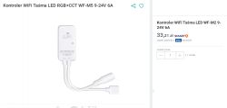
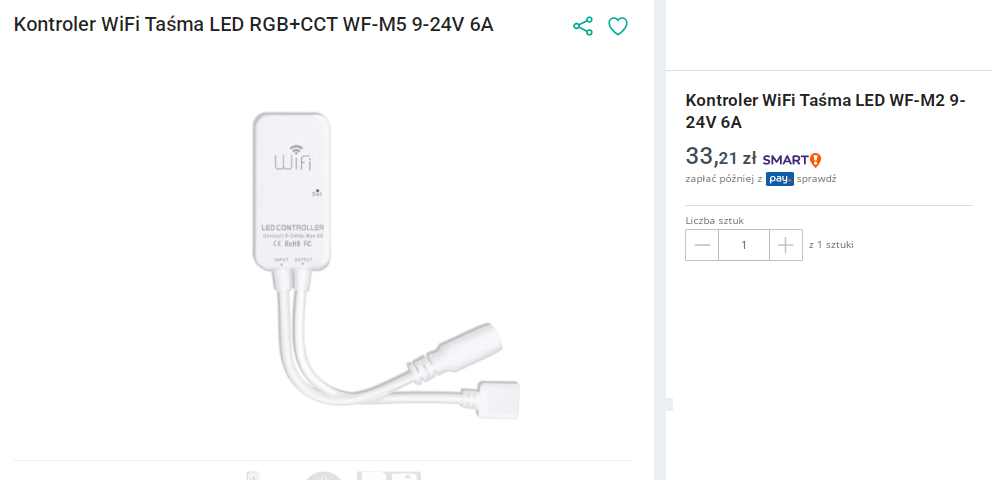
Why there is one thing in the title and another in the name of the subject - I don`t know. We definitely bought:
WiFi controller WF-M2 LED strip 9-24V 6A Quite a poor description:
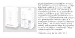
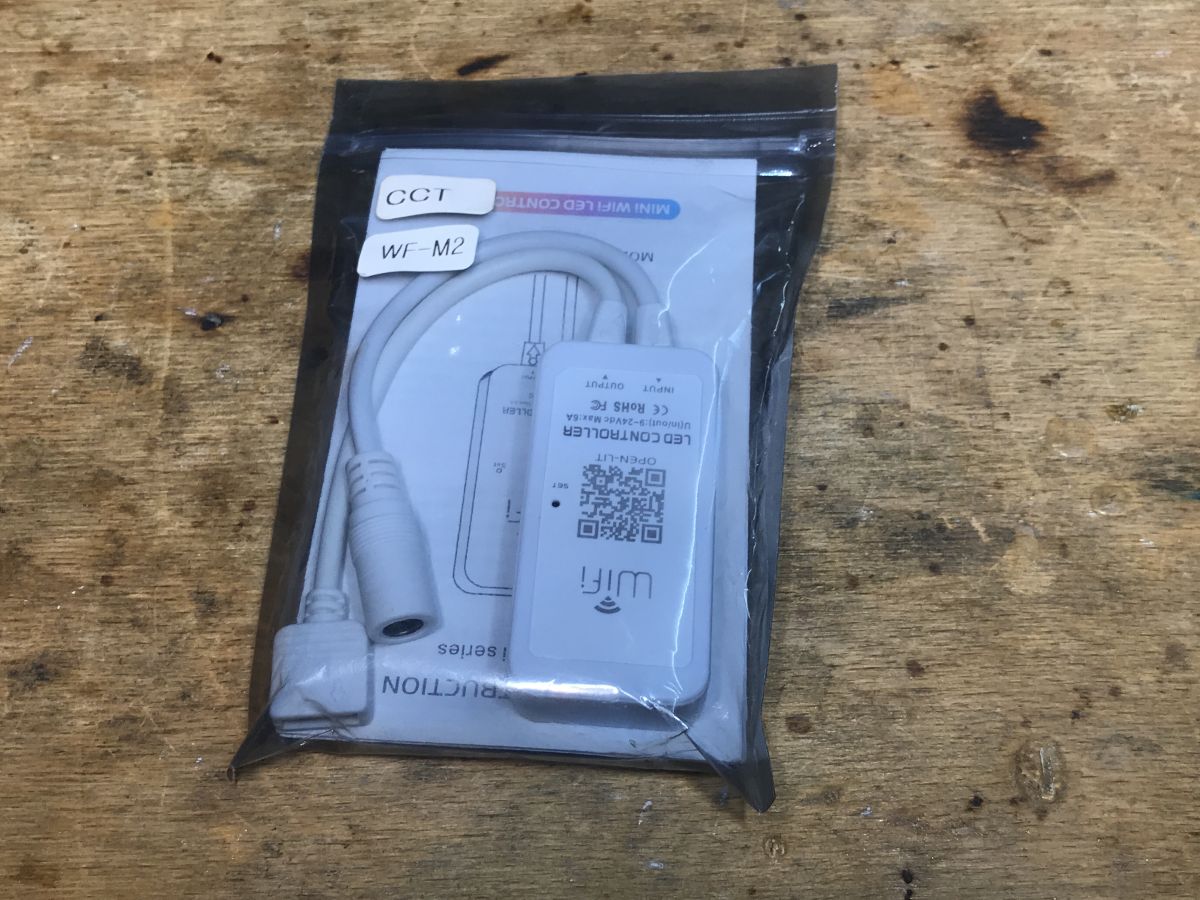
So let`s see what we get in the package:

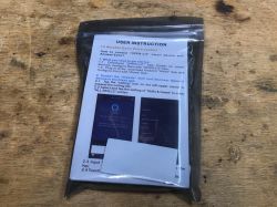
There is a CCT, WF-M2 sticker on the packaging, so it seems correct... let`s look at the instructions:

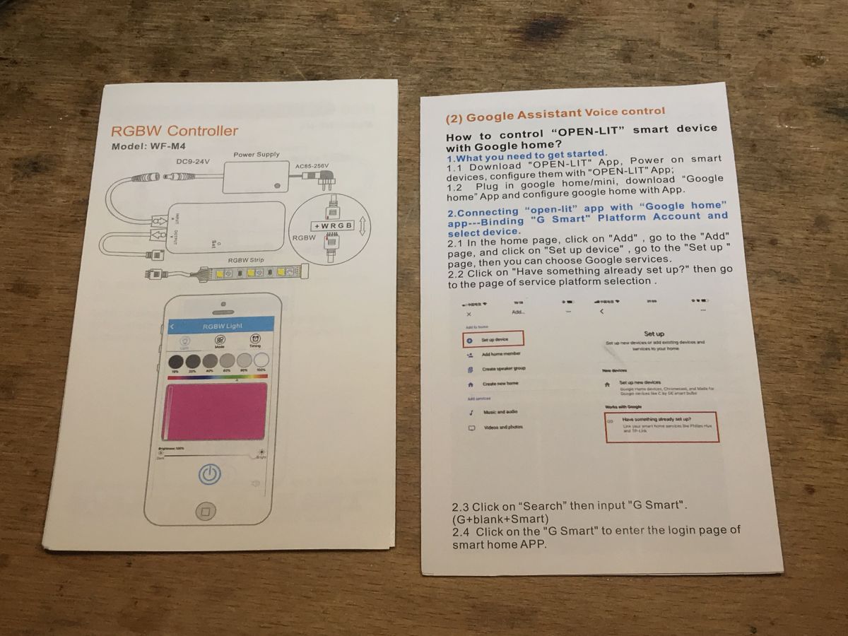
The manual contains the model
WF-M4 - it`s weird.
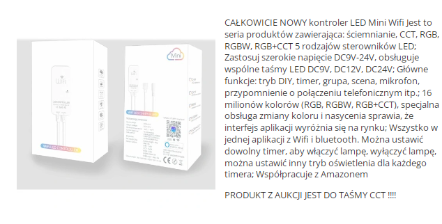
Additionally, we see that it needs to be linked to the Open-Lit application, perhaps another Tuya clone?
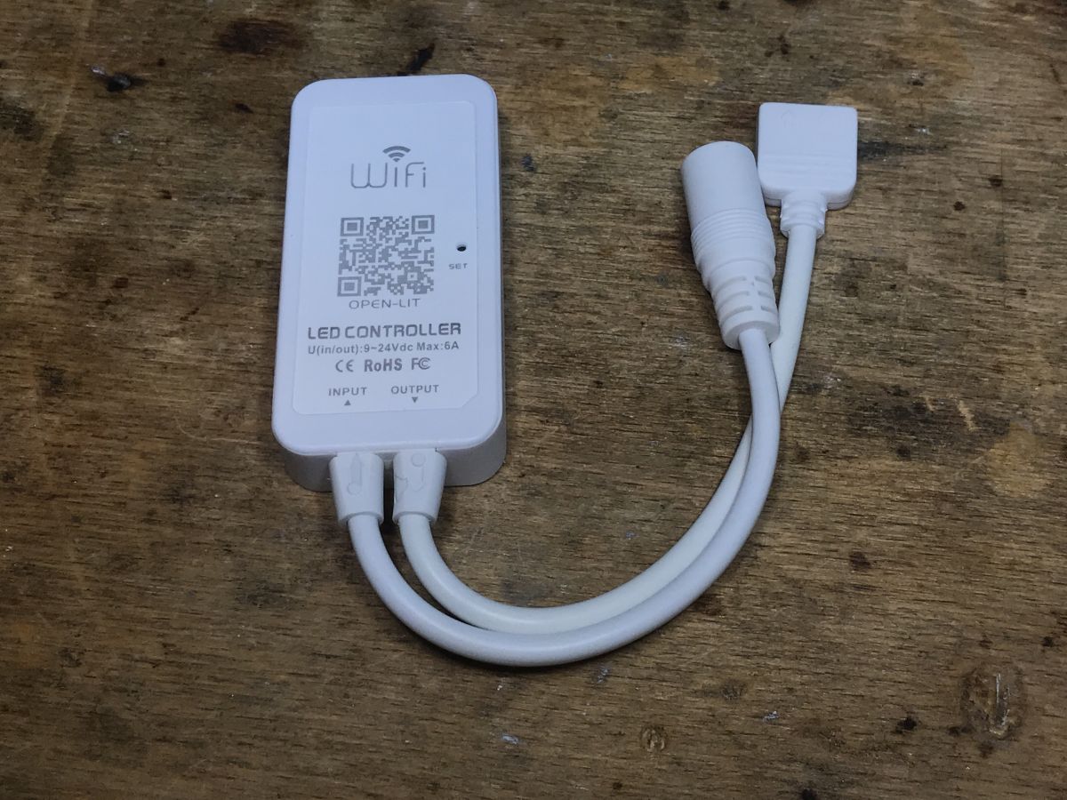
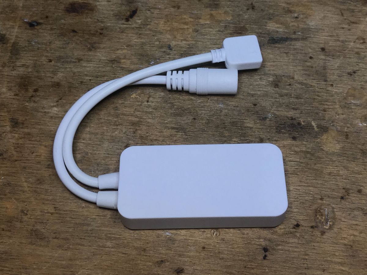
And the product itself:
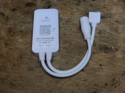

Everything is standard here, both the power input (jack socket) and the LED strip output...
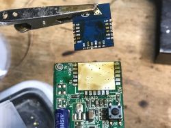
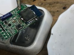
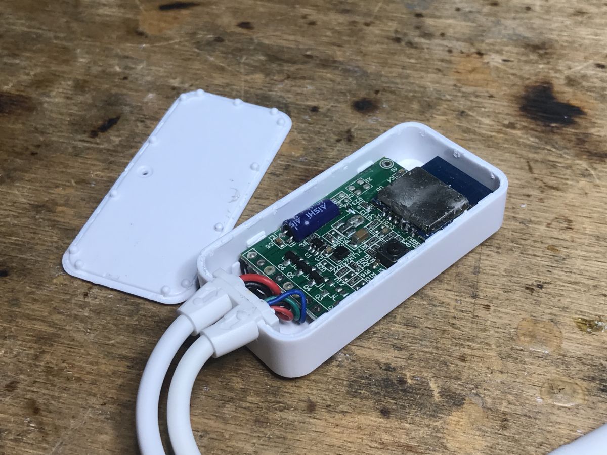
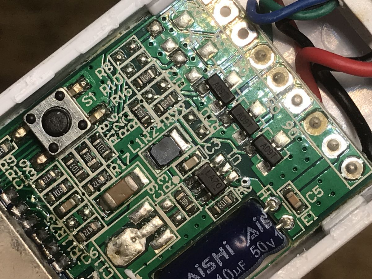
The interior of the WF-M2 (or rather WF-M4) There are no screws, just pry the lid with a flat screwdriver:
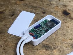
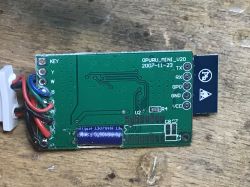
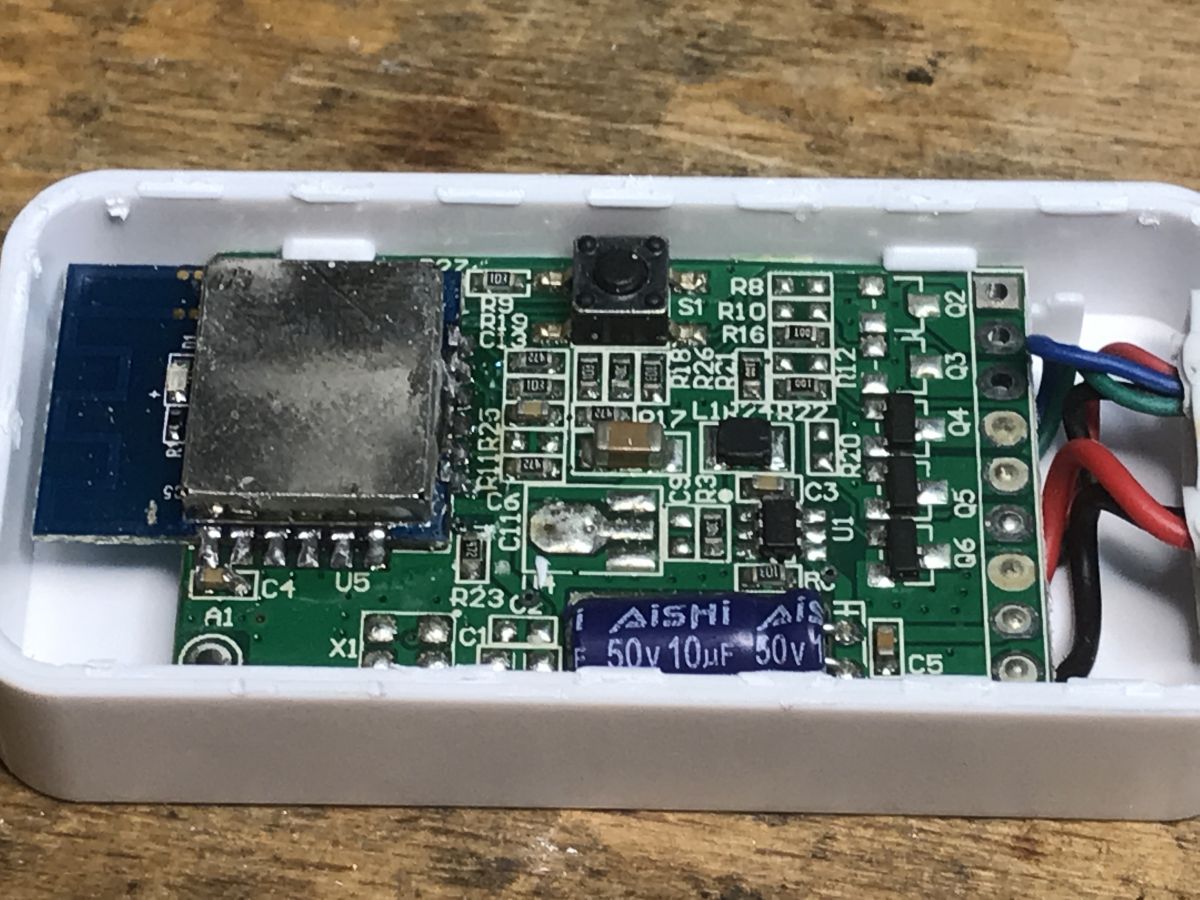
At first glance, the WiFi module is not described:

There are three transistors inside, so I don`t know if it`s really the CCT version... it looks like RGB:
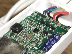
On the bottom we have the marking: OPURU_MINI_V20 2007-11-23, you can also see programming pads, including the characteristic IO0 - is it ESP8266?
I tried to solder it with programming cables, as usual, I described ESP programming on the forum via esptool.py:
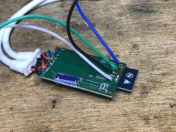
All you need is a USB to UART converter, connecting RX, TX, power supply and IO0 shorted to ground (during booting) to put the ESP in bootloader mode.
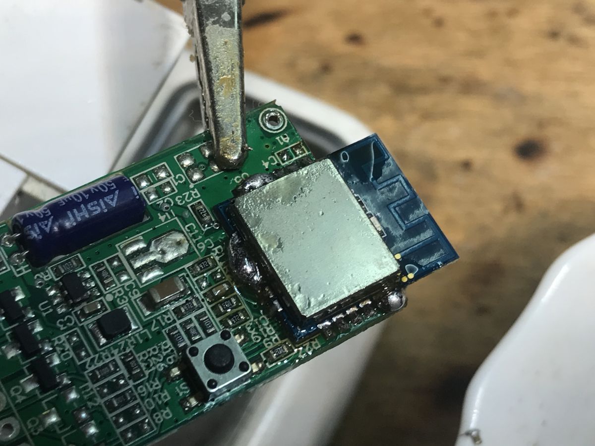
Success! Esptool recognized the system. Tasmota I managed to upload it, but the issue of the template remained... I decided to desolder the WiFi module to learn its markings. I applied additional flux and a bit of lead binder to the February:
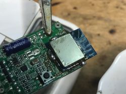
Hot air moves and after a while we have a desoldered module:
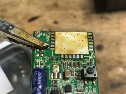
We can also see its outputs, they are signed on the descriptive layer:
This allowed us to identify the module - after all, it is LM1, its pins are documented on the network:

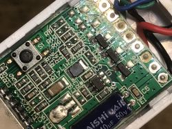
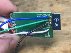
I also did a short analysis - where the path leads.

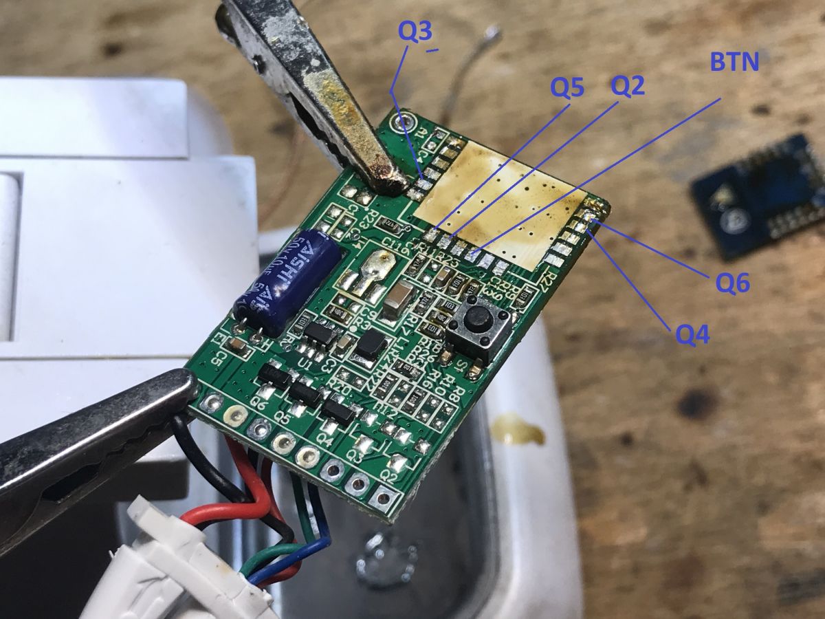
As you can see, this analysis will also be useful for the RGBCW version. I described all five transistors:
- Q2 - IO5 (not soldered on this board)
- Q3 - IO15 (not soldered on this board)
- Q4 - IO12
- Q5 - IO13
- Q6 - IO14
Additionally, I also mapped the button, but it seems to me that it is not marked correctly in the photo. If I find a moment, I will check the configuration of the bar and update the topic, and if not, you can try to trace the paths.
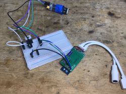
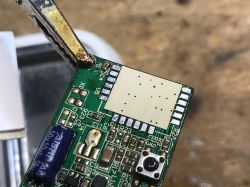
Finally, a nice photo taken before soldering the WiFi module into place (pads cleaned):
 Summary
 We bought the CCT version and got rather RGB - but that`s not a problem, it`s just one more transistor. In addition, the standard transistors are A09T, i.e. AO3400, you won`t get much out of them, the WiFi module is fortunately ESP and the programming pads are integrated. The advantage of this WF-M2 (or rather WF-M4) is the button on the housing, which allows us to control the LEDs even when WiFi stops working. In my opinion, this is quite important, because otherwise a router failure will paralyze the entire house, and this would defeat the whole point of playing "smart"? Some time ago, I even manually added buttons to strap controllers manufactured without them, changing the firmware makes this possible.


Comments