logo elektroda
logo elektroda
X
logo elektroda

New firmware for WT5 Multi-Channel LED controller with RF - TuyaMCU?

Kinsi55 7368 106
ADVERTISEMENT
  • #1 20686747
    Kinsi55
    Level 4  
    I bought a "WT5" Multi-Channel LED controller with RF remote support, I am curious if flashing this would be supported as I cannot find any information on it whatsoever: https://www.aliexpress.com/item/1005003394879757.html
    Image of the WT5 LED controller with RF remotes and other accessories, displayed on an online store page.

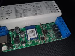
    From my quick look at the PCB, it looks like it's using a WB3S for Wi-Fi, another chip which I couldn't find any information about (20_cp6a71.1) for RF, and both of them feed into a SOC SC95F8615 that controls the Mosfets. This is just me guessing, I have not actually traced/investigated things. Attached is a picture of the PCB.

    I do have a Logic Analyzer so I could take a deeper look into things if necessary.

    Image of the LED controller WT5 PCB with a WB3S Wi-Fi module and four connection pins.
  • ADVERTISEMENT
  • #2 20686758
    p.kaczmarek2
    Moderator Smart Home
    Hello, can you do a 2MB flash dump so we can at least tell whether it's a TuyaMCU or are GPIOs of WiFi module used directly?

    TuyaMCU uses UART1 port of WiFi module to communicate with secondary MCU. Are TX1/RX1 pins of WB3S connected somewhere?
    Helpful post? Buy me a coffee.
  • #3 20686897
    Kinsi55
    Level 4  

    Hi, thanks for the quick response.

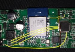
    I did some basic continuity testing. It seems like what you said is the case. TX1 of the WB3S connects to a transistor which connects to an I/O Pin of the secondary MCU. RX is not connected as far as I can tell.

    Also, the switch for setting the operation mode, as well as the status LED, connects to the secondary MCU. I will get a flash dump in a little bit.

    Close-up of a circuit board with highlighted TX1 and I/O connections on WB3S module.
  • #4 20687054
    p.kaczmarek2
    Moderator Smart Home
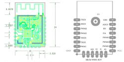
    Where do five MOSFETs controlled by PWM connect?

    Are they using PWM outputs of WB3S or the MCU?
    Technical diagram showing the bottom side of the WB3S module with pin assignments.
    NOTE: following is the image of WB3S BOTTOM SIDE.
    Helpful post? Buy me a coffee.
  • #5 20687084
    Kinsi55
    Level 4  

    They connect to the MCU. I reckon this is done because, like I said, this controller accepts inputs from both Tuya/Wifi and via RF remotes.
  • #6 20687286
    p.kaczmarek2
    Moderator Smart Home
    I think it's TuyaMCU device.

    I think you will see baud rate settings in Tuya JSON config.

    I also suspect that RF remote will still work after you change firmare of WiFi module, this is how TuyaMCU devices work.
    Helpful post? Buy me a coffee.
  • ADVERTISEMENT
  • #7 20687723
    Kinsi55
    Level 4  

    OK, I guess in this case I would have to use their app and capture all the communication that is happening?
  • #8 20687757
    p.kaczmarek2
    Moderator Smart Home
    It would certainly help. Most of the work was done in this topic:
    https://www.elektroda.com/rtvforum/topic3982779.html
    but still, captures of UART data during each Tuya app operation will be very useful, we need them to determine colour format, etc.
    Helpful post? Buy me a coffee.
  • #9 20688328
    Kinsi55
    Level 4  
    I have dumped the Flash, its attached. When I try to extract the config, this is what I get

    {
    	"wifi_bdrate":"115200",
    	"wifi_cofig_ver":"1.0.0",
    	"crc":"127",
    	"bt_mac":"null",
    	"bt_hid":"null",
    	"prod_test":"false "
    }


    Does this look like what you'd expect? Would I have to setup Wifi first before it will show me the TuyaMCU stuff?

    Nevermind, I just enabled the TuyaMCU analyzer at 115200 and it works, I will try to capture all packes / features. Where would I ideally share them once I'm done? Do I create a new thread?

    Edit2: Actually, I think to achieve what I want I will have to modify the LED controller. I want to split my lighting into two zones, which I thought would be possible since it has 5 Mosfets, and features WW/CW twice on the outputs for CCT output, but turns out they are just bridged, not seperate.

    I'll analyze the Communication of the RF receiver and see if I can figure out the protocol. How easy would it be to modify OpenBeken to receive the Data from the RF receiver? I would then just directly connect the mosfets to the WB3S and disable the secondary MCU.
  • #10 20688417
    p.kaczmarek2
    Moderator Smart Home
    I have split the topic for you right now, so there is no need to create another one.

    Sharing TuyaMCU captures here will help, even if you want to modify the device. There are other users and readers who could benefit from this data.

    Using TuyaMCU to control this device is a much easier way. Most likely everything is already in firmware for that.
    Using RF with OBK directly is not currently supported. It's planned, but it requires some real programming work and it would also require me to have this device physically with me, so I can test efficiently.

    Still, if you can do some kind of RF capture to show how the data is formatted, feel free to do it.
    Helpful post? Buy me a coffee.
  • #11 20689106
    Kinsi55
    Level 4  

    Thanks for splitting the topic.

    I have set the controller into DIM mode (Single Channel control) and CCT mode (Warm+Cold white) and captured the TuyaMCU communication, it's attached. I have not bothered to capture RGB / RGBW / RGBCCT because the output looked pretty similar but I could do that later if desired (I've included notes as to which action was done in the output).

    I have also gone ahead and traced all the connections between the RF Chip and the secondary MCU and connected my logic analyzer. Unfortunately, I have no clue what the protocol could be.

    There are 5 connections between the RF Chip and the MCU. The most sensible thing to me is that it is SPI with a 5th connection being something like Enable or Receive / Transmit (Because these controllers re-transmit everything that they receive, and if I remove power from the secondary MCU, no data is output).

    Attached are screenshots of what I captured when I press a button on the remote (Channel 1 Button).

    I have also attached the capture data where I press Button 1 and then Button 2, it can be opened with Logic: https://www.saleae.com/downloads/

    Screenshot of a logic interface with signals on five channels. Screenshot of a logic analyzer showing signals on five channels. Screenshot of a waveform from a logic analysis of electronic signals for a controller.
  • #12 20689159
    p.kaczmarek2
    Moderator Smart Home
    Nice, but we really need more information. This may be SPI with extra INT line where RF chip gives interrupt signal to MCU when something is received:
    Digital oscilloscope captures of five digital signal channels.
    We have both hardware and software SPI working, so if we'd know the details it would be possible to support it as well. Still, I'd prefer to first focus on TuyaMCU, at least for the other users...

    We also need more TuyaMCU captures, including RGB.
    So far I can see:
    fnId=20 Bool V=1 CHK - ON/OFF
    fnId=28 Str V=31 30 30 30 30 30 30 30 30 30 30 30 30 30 30 31 34 30 33 65 38 CHK - color in Tuya format ASCII? 0x30 is ASCII 0
    fnId=21 Enum V=0 CHK - idk, maybe it's a mode enum? CW vs RGB?
    fnId=22 Val V=15 CHK - idk, maybe brightness?
    fnId=23 Val V=1000 CHK - idk, maybe temperature? it changes from 7 to 1000 in CCT.txt

    I also must look up that Tuya color format... as per Tasmota:
    
          // There are two types of rgb format, configure the correct one using TuyaRGB command.
          // The most common is 0HUE0SAT0BRI0 and the less common is RRGGBBFFFF6464 and sometimes both are case sensitive:
          // 0  type 1 Uppercase - 00DF00DC0244
          // 1  Type 1 Lowercase - 008003e8037a
          // 2  Type 2 Uppercase - 00FF00FFFF6464
          // 3  Type 2 Lowercase - 00e420ffff6464
    

    Hmm it doesn't seem to match your captures. How would first RED, then GREEN, and then BLUE look like for your device?
    Helpful post? Buy me a coffee.
  • ADVERTISEMENT
  • #14 20689192
    Kinsi55
    Level 4  

    I've gone ahead and configured it in RGB + CCT Mode, unfortunately color is a wheel and not separate R/G/B values so I had to approximate where I click on the Wheel:

    All of these are full brightness:

    In case this matters: I just noticed that I captured these (TX line of the WB3S) using the RX option in the Analyzer

    Switching to RGB Mode:
    55 AA	00	06		00 05	1504000101	25	
    HEADER	VER=00	SetDP		LEN	fnId=21 Enum V=1	CHK	

    Red:
    55 AA	00	06		00 19	1C030015313030303030336538303365383030303030303030	C3	
    HEADER	VER=00	SetDP		LEN	fnId=28 Str V=31 30 30 30 30 30 33 65 38 30 33 65 38 30 30 30 30 30 30 30 30	CHK
    55 AA	00	06		00 05	1504000101	25	
    HEADER	VER=00	SetDP		LEN	fnId=21 Enum V=1	CHK	
    55 AA	00	06		00 10	1803000C303030303033653830336538	FC	
    HEADER	VER=00	SetDP		LEN	fnId=24 Str V=30 30 30 30 30 33 65 38 30 33 65 38	CHK	

    Green:
    55 AA	00	06		00 19	1C030015313030373330336538303365383030303030303030	CD	
    HEADER	VER=00	SetDP		LEN	fnId=28 Str V=31 30 30 37 33 30 33 65 38 30 33 65 38 30 30 30 30 30 30 30 30	CHK
    55 AA	00	06		00 05	1504000101	25	
    HEADER	VER=00	SetDP		LEN	fnId=21 Enum V=1	CHK	
    55 AA	00	06		00 10	1803000C303037333033653830336538	06	
    HEADER	VER=00	SetDP		LEN	fnId=24 Str V=30 30 37 33 30 33 65 38 30 33 65 38	CHK	
    

    Blue:
    55 AA	00	06		00 19	1C030015313030653130336538303365383030303030303030	F9	
    HEADER	VER=00	SetDP		LEN	fnId=28 Str V=31 30 30 65 31 30 33 65 38 30 33 65 38 30 30 30 30 30 30 30 30	CHK
    55 AA	00	06		00 05	1504000101	25	
    HEADER	VER=00	SetDP		LEN	fnId=21 Enum V=1	CHK	
    55 AA	00	06		00 10	1803000C303065313033653830336538	32	
    HEADER	VER=00	SetDP		LEN	fnId=24 Str V=30 30 65 31 30 33 65 38 30 33 65 38	CHK	

    Switching to CCT:
    55 AA	00	06		00 05	1504000100	24	
    HEADER	VER=00	SetDP		LEN	fnId=21 Enum V=0	CHK	

    Full Warm-White:
    55 AA	00	06		00 19	1C030015313030303030303030303030303033653830303030	83	
    HEADER	VER=00	SetDP		LEN	fnId=28 Str V=31 30 30 30 30 30 30 30 30 30 30 30 30 30 33 65 38 30 30 30 30	CHK
    55 AA	00	06		00 05	1504000100	24	
    HEADER	VER=00	SetDP		LEN	fnId=21 Enum V=0	CHK	
    55 AA	00	06		00 08	1702000400000000	2A	
    HEADER	VER=00	SetDP		LEN	fnId=23 Val V=0	CHK	

    Full Cold-White:
    55 AA	00	06		00 19	1C030015313030303030303030303030303033653830336538	C3	
    HEADER	VER=00	SetDP		LEN	fnId=28 Str V=31 30 30 30 30 30 30 30 30 30 30 30 30 30 33 65 38 30 33 65 38	CHK
    55 AA	00	06		00 05	1504000100	24	
    HEADER	VER=00	SetDP		LEN	fnId=21 Enum V=0	CHK	
    55 AA	00	06		00 08	17020004000003E7	14	
    HEADER	VER=00	SetDP		LEN	fnId=23 Val V=999	CHK	


    Judging from this:

    - fnId 21 dictates if we are sending RGB (0) or CCT/White (1)
    - fnId 23 dictates if it's Warm White (0) or Cold White (1000)

    Additional things I figured out:

    - fnId 20 is on / off just like with the remote
    - fnId 22 is brightness, just like with the remote

    >>20689190

    Here is RX of the WB3S when pressing keys on the CCT Remote (I don't have an RGB remote), these are "detected":

    - On / Off: ID 20, Type 1 (Bool), 0/1
    - Brightness: ID 22, Type 2 (Val), Min 31, Max 1000
    - Color Temperature: ID 23, Type 2 (Val), Min 0, Max 1000

    Unfortunately, the different Zone buttons or Scene buttons do not send anything, they are probably handled within the MCU because as I realized, the Controller is only built to be one Zone so this is something I'd have to solve at some point in some way (Not sure if OpenBeken supports multiple Lighting Zones)

  • #15 20689271
    p.kaczmarek2
    Moderator Smart Home
    Using RX instead of TX in analyzer won't make big difference.

    Very good job, all we need to know now is how to generate that ASCII strings:

    
    55 AA	00	06		00 19	1C030015313030373330336538303365383030303030303030	CD	
    HEADER	VER=00	SetDP		LEN	fnId=28 Str V=31 30 30 37 33 30 33 65 38 30 33 65 38 30 30 30 30 30 30 30 30	CHK
    
    55 AA	00	06		00 05	1504000101	25	
    HEADER	VER=00	SetDP		LEN	fnId=21 Enum V=1	CHK	
    
    55 AA	00	06		00 10	1803000C303037333033653830336538	06	
    HEADER	VER=00	SetDP		LEN	fnId=24 Str V=30 30 37 33 30 33 65 38 30 33 65 38	CHK	
    

    It seems there are two variables for colors, and fn24 is only for RGB?

    This:
    V=30 30 37 33 30 33 65 38 30 33 65 38
    translates to:
    00 73 03 e8 03 e8
    And it's green, right?
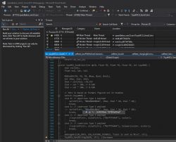
    Let me try in simulator:
    
    tuyaMCU_sendColor 24 0 1 0 1
    

    Yes, I know that format:
    Screenshot of Visual Studio with code related to TuyaMCU_SendColor.
    This is the same as in this topic:
    https://www.elektroda.com/rtvforum/topic3982779.html#20656814
    Even dpID is the same - 24....

    Maybe the approach from that topic can work here and no code changes are required.

    I am still unsure about dpID 28.
    Helpful post? Buy me a coffee.
  • #16 20689285
    Kinsi55
    Level 4  

    p.kaczmarek2 wrote:
    I am still unsure about dpID 28.


    If 30 30 37 33 30 33 65 38 30 33 65 38 is RGB / Green, and it's present 1:1 in 28, I think the 8 bytes at the end of 28 might be Warm White / Cold White (+brightness?) since they are all 0x30 when in RGB mode, vice versa RGB values are 0x30 in CCT mode.

    I'm not sure why they transmit RGB / WW+CW twice (In two values) though.
  • #17 20699042
    Kinsi55
    Level 4  
    I have flashed OpenBeken now and tried to set it up using the commands in the other Thread.

    As expected, controlling via the Remote still works, however now there is no more TuyaMCU communication sent to the WB3S when I press buttons on the remote, and also nothing that I click in the webinterface has any effect.

    tuyaMcu_sendQueryState also does not have any output.

    How should I proceed?
  • #18 20699054
    p.kaczmarek2
    Moderator Smart Home
    Hello, what is your current autoexec bat?

    Are you setting the correct baud rate?
    Helpful post? Buy me a coffee.
  • #19 20699088
    Kinsi55
    Level 4  
    I did forget setting the baud rate, my bad.

    With that done, tuyaMcu_sendQueryState returns this
    Info:TuyaMCU:TUYAMCU received: 55 AA 03 00 00 01 01 04 
    Info:TuyaMCU:TuyaMCU_ProcessIncoming[ver=3]: processing command 0 (Hearbeat) with 8 bytes
    Info:TuyaMCU:TUYAMCU received: 55 AA 03 07 00 05 14 01 00 01 01 25 
    Info:TuyaMCU:TuyaMCU_ProcessIncoming[ver=3]: processing command 7 (State) with 12 bytes
    Info:TuyaMCU:TuyaMCU_ParseStateMessage: processing dpId 20, dataType 1-DP_TYPE_BOOL and 1 data bytes
    Info:TuyaMCU:TuyaMCU_ParseStateMessage: raw data 1 byte: 
    Info:TuyaMCU:TUYAMCU received: 55 AA 03 07 00 05 15 04 00 01 00 28 
    Info:TuyaMCU:TuyaMCU_ProcessIncoming[ver=3]: processing command 7 (State) with 12 bytes
    Info:TuyaMCU:TuyaMCU_ParseStateMessage: processing dpId 21, dataType 4-DP_TYPE_ENUM and 1 data bytes
    Info:TuyaMCU:TuyaMCU_ParseStateMessage: raw data 1 byte: 
    Info:TuyaMCU:TUYAMCU received: 55 AA 03 07 00 08 16 02 00 04 00 00 03 E8 18 
    Info:TuyaMCU:TuyaMCU_ProcessIncoming[ver=3]: processing command 7 (State) with 15 bytes
    Info:TuyaMCU:TuyaMCU_ParseStateMessage: processing dpId 22, dataType 2-DP_TYPE_VALUE and 4 data bytes
    Info:TuyaMCU:TuyaMCU_ParseStateMessage: raw data 4 int: 1000
    Info:TuyaMCU:TUYAMCU received: 55 AA 03 07 00 08 17 02 00 04 00 00 03 E8 19 
    Info:TuyaMCU:TuyaMCU_ProcessIncoming[ver=3]: processing command 7 (State) with 15 bytes
    Info:TuyaMCU:TuyaMCU_ParseStateMessage: processing dpId 23, dataType 2-DP_TYPE_VALUE and 4 data bytes
    Info:TuyaMCU:TuyaMCU_ParseStateMessage: raw data 4 int: 1000
    Info:TuyaMCU:TUYAMCU received: 55 AA 03 07 00 08 1A 02 00 04 00 00 00 00 31 
    Info:TuyaMCU:TuyaMCU_ProcessIncoming[ver=3]: processing command 7 (State) with 15 bytes
    Info:TuyaMCU:TuyaMCU_ParseStateMessage: processing dpId 26, dataType 2-DP_TYPE_VALUE and 4 data bytes
    Info:TuyaMCU:TuyaMCU_ParseStateMessage: raw data 4 int: 0


    This is now my Autoexec:
    startDriver TuyaMCU
    tuyaMcu_setBaudRate 115200
    tuyaMcu_setDimmerRange 0 1000
    
    // ON/OFF
    setChannelType 20 toggle
    // RGB(0) White(1)
    setChannelType 21 toggle
    // Brightness
    setChannelType 22 dimmer
    // Warm White (0) or Cold White (1000)
    setChannelType 23 dimmer
    
    linkTuyaMCUOutputToChannel 20 1 20
    linkTuyaMCUOutputToChannel 21 1 21
    linkTuyaMCUOutputToChannel 22 2 22
    linkTuyaMCUOutputToChannel 23 2 23


    I am unsure how to make the dimmers "special" (So for coldwhite / warmwhite as can be seen in some screenshots)

    However, the Problem still remains that buttons pressed on the Remote are not sent to the WB3S
  • #20 20699097
    p.kaczmarek2
    Moderator Smart Home
    This is because device must think it's paired and connected to the cloud. You need to either connect to MQTT or add this to autoexec.bat:
    
    tuyaMcu_defWiFiState 4
    
    Helpful post? Buy me a coffee.
  • #21 20699117
    Kinsi55
    Level 4  

    I was connected to MQTT, but it looks like rebooting the controller fixed it. Remote inputs are now received by the WB3S. I suppose I can now tinker around and see if I can somehow implement two zones into this single controller. Thank you.

    Added after 1 [hour] 34 [minutes]:

    I've checked how the output Mosfets are wired up on the controller. They have a 28k resistor from Gate to Ground, and a 47 Ohm from the secondary MCU to Gate.

    Would it be possible to have an output role in OpenBeken that can be toggled between being Open Drain / not? This would be the easiest way to allow the other Mosfets to be forced off because you would just need to replace the 47 Ohm resistor with like 470 Ohm and connect the Gate to a WB3S I/O pin additionally, and when that is switched into Open Drain it would of course Pin the Gate to GND - I would think it can sink the 10mA current which that would cause.

    Alternatively, I would need to either add a Relay or another Mosfet which of course makes it more complicated.

    Another way could be wiring the Mosfets of the second channel directly to the WB3S and it would then control those channels itself. And since it receives the remote values from the secondary MCU via TuyaMCU, it can just apply the same values.
  • #22 20699179
    p.kaczmarek2
    Moderator Smart Home
    It may be possible to be done with scripting. You would need to alternate between those pin roles:
    - AlwaysHigh
    - AlwaysLow
    - DigitalInput_NoPup
    See: https://github.com/openshwprojects/OpenBK7231T_App/blob/main/docs/ioRoles.md

    You could write a script that watches given channel and sets the role of each output when required, but maybe first try to check if it works just by changing roles on HTTP panel.
    Helpful post? Buy me a coffee.
  • #23 20700163
    Kinsi55
    Level 4  

    Ok, that is something I can figure out later, for now I'd need to be able to receive the remote signals. Gamalot over in the EEVBlog forums was able to identify the chip and found a Datasheet for it: https://datasheetspdf.com/pdf-file/1480873/ETC/LT8900SSK/1

    With that, I was able to confirm that the communication is SPI, and with the right settings, Logic can actually properly parse the communication. I've attached a new Logic capture with some button presses / Notes on them and setup Analyzer. The fifth pin was just what you thought, a signal for when data is received (PKT/13)

    Pressing the same Channel Button multiple times sends the same Data, so what I need to do now is receive this SPI communication on the WB3S, and when it detects that the Channel 2 Button was pressed, it needs to change an I/O pin in one way or another. For testing, I would just connect a relay for now, maybe later I would switch that to the Open Drain "Hack"

    Edit: I just noticed my Soldering failed, which is why there is no MISO communication in that capture, I've fixed that and attached a new one :D
  • ADVERTISEMENT
  • #24 20700164
    p.kaczmarek2
    Moderator Smart Home
    It would be very cool if we've managed to get that driver running. I can help you with some basics guidance. Do you have some C experience?
    Helpful post? Buy me a coffee.
  • #25 20700177
    Kinsi55
    Level 4  
    Yes, I do have some C/C++ experience. I've done some basic embedded work before with Atmegas and STM32's.

    What I am wondering is, would I be able to only listen to the RF > MCU SPI communication on the WB3S and have the secondary MCU continue to handle it? I've never worked with SPI before in this fashion and this would be my preferred implementation.

    As it stands, theres only a hand full of free pins on the WB3S:

    - EN
    - TXD2
    - RXD2
    - PWM3

    That would be enough for full SPI communication, but then I'd have no way of actually adding a relay, or if we could ignore MOSI or MISO, that would free up a pin for that (Hence, only listening to the communication)

    Also all the ones on the Bottom edge, so SO, SI, CS, SCK but I dont think those are usable?
  • #26 20700952
    p.kaczmarek2
    Moderator Smart Home
    All WB3S pins are useable, including:
    Pin No.SymbolI/O TypeFunction
    1SOI/OData output pin when data is downloaded from the flash memory, which is used for module production and firmware burning and is connected to the P23 or ADC3 pin on the internal IC
    2SII/OData input pin when data is downloaded from the flash memory, which is used for module production and firmware burning and is connected to the P22 pin on the internal IC
    3CSI/OChip selection pin when data is downloaded from the flash memory, which is used for module production and firmware burning and is connected to the P21 pin on the internal IC
    4SCKI/OClock pin when data is downloaded from the flash memory, which is used for module production and firmware burning and is connected to the P20 pin on the internal IC

    We have even used them in this video:
    https://youtu.be/KU0tDwtjfjw?t=235

    It's good to hear you have programming experience. There are few things you can check to get better understanding of the codebase:
    - BL0942 driver can work in both UART (default) and hardware SPI mode:
    https://github.com/openshwprojects/OpenBK7231T_App/blob/main/src/driver/drv_bl0942.c
    - here is SPI driver itself:
    https://github.com/openshwprojects/OpenBK7231T_App/blob/main/src/driver/drv_spi.c
    - here is a driver that is using GPIO interrupt:
    https://github.com/openshwprojects/OpenBK7231T_App/blob/main/src/driver/drv_bl0937.c

    I am currently not sure how exactly we should handle the communication, but most likely first you'd need to setup an interrupt on GPIO and when it's fired use SPI to communicate with the chip.

    BK7231 SPI is only on certain pins, so maybe it would be better to use a software SPI?
    https://github.com/openshwprojects/OpenBK7231T_App/blob/main/src/driver/drv_soft_spi.c
    Here is a sample driver that uses software SPII:
    https://github.com/openshwprojects/OpenBK7231T_App/blob/main/src/driver/drv_spi_flash.c
    I didn't check the datasheet of your RF module yet, but maybe it would be enough to use one interrupt and the software SPI...
    Helpful post? Buy me a coffee.
  • #27 20701602
    Kinsi55
    Level 4  

    Unless I'm mistaken, it looks like the implementation does not currently support being an SPI Slave, right?

    As mentioned before, the RF Chip is connected to the secondary MCU, which is the master - So ideally, I would just have the WB3S be another SPI Slave and just listen to the communication happening between both of them (I know I could then only listen on MOSI or MISO but that should be enough).

    I guess the easiest way would be having an interrupt on the SPI Clock and then appending the read values into some kind of buffer.
  • #28 20701840
    p.kaczmarek2
    Moderator Smart Home
    I don't think it supports SPI slave mode, but:

    Kinsi55 wrote:

    As mentioned before, the RF Chip is connected to the secondary MCU, which is the master - So ideally I would just have the WB3S be another SPI Slave and just listen to the communication happening between both of them (I know I could then only listen on MOSI or MISO but that should be enough)

    maybe it would be easier to remove the MCU, connect the 5 PWMs to PWM pins of WB3S and the 5 SPI pins to any other pins (or the hardware SPI of BK, if needed) and implement everything on BK?

    I may be wrong, but I don't think this device requires quick SPI communication. Bit-bang software SPI could be enough...
    Helpful post? Buy me a coffee.
  • #29 20702604
    Kinsi55
    Level 4  

    I was trying to avoid doing that for a couple of reasons:

    - It would require quite a lot of modification, so others would be less likely to do it and undoing it wouldn't be super easy either if desired
    - The secondary MCU starts up really quick when power is applied and fades in back to the previous state - Not sure how much delay there would be with the WB3S
    - I'm not sure there would be enough I/O for that (There's the 4 Pins at the bottom + the 3 that are free right now + RX/TX, that's 9. With 5 Mosfets it would leave 4 for the SPI, but no more for the Interrupt pin and you cannot connect anything else either if you wanted to)

    My goal right now is to detect on the WB3S when the Channel 2 Button is pressed and toggle the secondary channel based off that
  • #30 20715579
    Kinsi55
    Level 4  

    Do you have any idea if the WB3S is 5V tolerant? According to the Tuya datasheet, the max I/O Input Voltage is 3.6, but according to Espressif, the ESP32 doesn't support 5V either, yet it tolerates it just fine - So I'm wondering if you know if that is the case for the WB3S as well.

    I'm asking because the Secondary MCU -> RF Chip logic level is 5V. Not needing to convert that would of course be great :D

    I have figured out the communication mostly and it should be very possible to just passively listen to it and attach functions in Openbeken to remote buttons - Which is what I was gonna do / create a driver for.

    When a Packet arrives, first 0b1011 0000 is sent, which is REGISTER_READ | R_STATUS (48)
    RETURN:
    15 CRC_ERROR R Received CRC error
    14 FEC23_ERROR R Indicate FEC23 error
    13:8 FRAMER_ST R Framer status
    7 SYNCWORD_RECV R 1: syncword received, it is just available in receive status, After out receive status, always keep ‘0’.
    6 PKT_FLAG R PKT flag indication
    5 FIFO_FLAG R FIFO flag indication
    4:0 (Reserved) R (Reserved)
    If STATUS_CRC_BIT (15) is true, the data is just discarded
    else it will then read register 50 (R_FIFO)
    RETURN:
    15:0 TXRX_FIFO_REG R/W
    For MCU read/write data between the FIFO.
    Reading this register removes data from FIFO; Writing to this
    register adds data to FIFO.
    Note: FW (MCU) access to FIFO is byte-by-byte.
    data >> 8 of the first response is the packet size
    Afterwards, this read is repeated until packetSize is met
    and data just gets appended into a buffer
    Once that is over...
    first 0b0011 0100 is sent which is REGISTER_WRITE | R_FIFO_CONTROL
    The data that is written is 0b1000 0000 which just clears the FIFO buffer
    After that, another write to register 7, sending 0b0000 0000, 0b11001100
    I have no clue yet what that does, but it's not really relevant for us

Topic summary

The discussion revolves around the WT5 Multi-Channel LED controller, which utilizes a WB3S Wi-Fi module and an SC95F8615 SOC for controlling MOSFETs. Users are exploring the possibility of flashing the device with new firmware, specifically OpenBeken, to enable better integration with TuyaMCU. Key points include the need for UART communication captures to understand the device's operation, the challenges of RF remote control integration, and the behavior of the device upon power cycling. Users have shared their experiences with firmware flashing, configuration scripts, and the limitations of the current setup, particularly regarding the synchronization of settings between the RF remote and the web interface. Solutions discussed include modifying the autoexec.bat for persistent settings and capturing communication data for further analysis.
Summary generated by the language model.
ADVERTISEMENT