 .
.
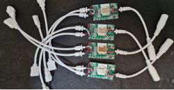
My colleague @DeDaMrAz and I bought some Tuya LED strip controllers to convert them to work with Home Assistant. Here I will show how to change their batch, configure their GPIO and also how to handle IR (remote control) events in OpenBeken . In addition, we'll also take a look inside the power supply - how much has the Chinese saved on it?
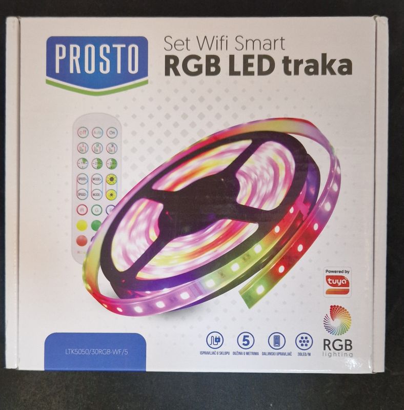
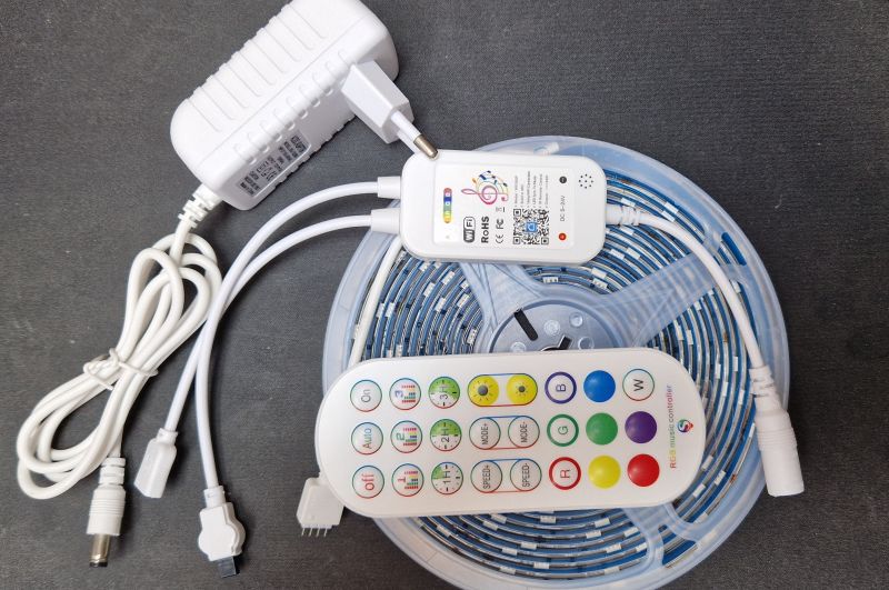
Let's start with the kit presentation. That's what you get for €18:
 .
.
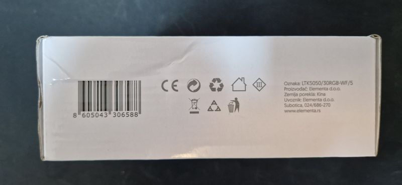
Designation:
 .
.
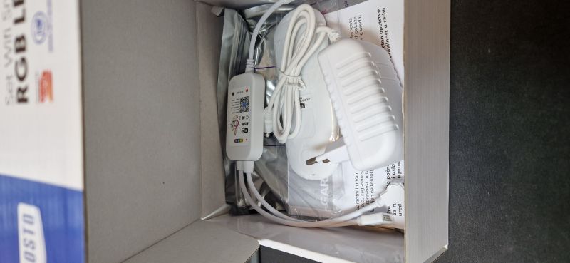
There is also an LED strip and remote control inside, and even a power supply:
 .
.
The remote control included has a battery.
 .
.
Interior, OpenBeken upload, GPIO .
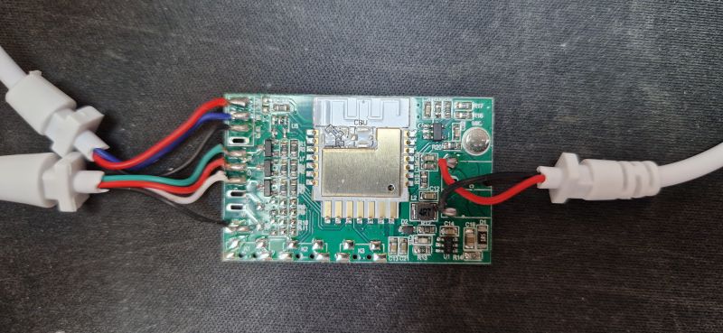
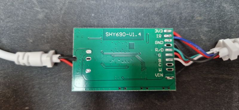
The casing is a snap. We take a look inside:
 .
.
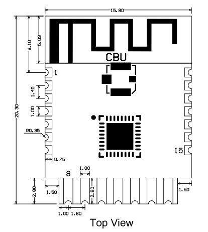
Inside is the CBU module, which is BK7231N . Here is the CBU pinout:
 .
.
Its pinouts (from Tuya documentation; untranslated):
| Pin number | . Symbol | I/O type | Function | ||
| 1 | 1 | P14 | I/O | Common GPIO, which can be reused as SPI_SCK (Correspond to Pin 11 of the IC) | |
| 2 | P16 | I/O | Common GPIO, which can be reused as SPI_MOSI (Correspond to Pin 12 of the IC) | ||
| 3 | P20 | I/O | Common GPIO (Correspond to Pin 20 of the IC) | ||
| 4 | P22 | I/O | Common GPIO (Correspond to Pin 18 of the IC) | ||
| 5 | ADC | I/O | ADC, which corresponds to P23 on the internal IC (Correspond to Pin 17 of the IC) | ||
| 6 | RX2 | I/O | UART_RX2, which corresponds to P1 on the internal IC. (Correspond to Pin 28 of the IC) | ||
| 7 | TX2 | I/O | UART_TX2, which is used for outputting logs and corresponds to P0 of the internal IC (Correspond to Pin 29 of the IC) | ||
| 8 | P8 | I/O | Support hardware PWM (Correspond to Pin 24 of the IC) | ||
| 9 | P7 | I/O | P7Support hardware PWM (Correspond to Pin 23 of the IC) | ||
| 10 | P6 | I/O | Support hardware PWM (Correspond to Pin 22 of the IC) | ||
| 11 | P26 | I/O | Support hardware PWM (Correspond to Pin 15 of the IC) | ||
| 12 | P24 | .I/O | Support hardware PWM (Correspond to Pin 16 of the IC) | ||
| 13 | GND | P | P | Power supply ground reference Power supply reference ground | |
| 14 | 3V3 | P | Power supply 3V3 | ||
| 15 | TX1 | I/O | UART_TX1, which is used for transmitting user data and corresponds to Pin 27 of the IC. For the MCU solution, please refer to CBx Module. | ||
| 16 | RX1 | I/O | UART_RX1, which is used for receiving user data and corresponds to Pin 26 of the IC. For the MCU solution, please refer to CBx Module. | ||
| 17 | . P28 | I/O | Common GPIO (Correspond to Pin 10 of the IC) | ||
| 18 | |||||
| 18 | CEN | I/O | Reset pin, low active (internally pulled high), compatible with other modules (Correspond to Pin 21 of the IC) | ||
| 19 | P9 | I/O | . Common GPIO (Correspond to Pin 25 of the IC) | ||
| 20 | P17 | I/O | Common GPIO, which can be reused as SPI_MISO (Correspond to Pin 14 of the IC) | ||
| 21 | P15 | I/O | Common GPIO, which can be reused as SPI_CS (Correspond to Pin 13 of the IC) | ||
| Test point | CSN | I/O | Mode selection pin. If it is connected to the ground before being powered on, enter the firmware test mode. If it is not connected or connected to VCC before being powered on, enter the firmware application mode. Correspond to Pin 19 on the internal IC. |
We uploaded OpenBeken to:
https://github.com/openshwprojects/OpenBK7231T_App
Following the Flashers instructions:
https://github.com/openshwprojects/BK7231GUIFlashTool
You can also watch our instructional videos, especially those under BK7231N:
https://www.youtube.com/watch?v=L6d42IMGhHw&a...czAXT94BuSGrd_GoM&ab_channel=Elektrodacom
Thus, we first made a copy of the batch of all four devices, available here:
https://github.com/openshwprojects/FlashDumps/commit/dd22f9c6b013a32e96f7e23ccbd2e5c719571104
and then we uploaded the OBK.
OpenBeken template:
Code: JSON
Tutorial for uploading the template:
Everything works, also with Home Assistant, see OBK pairing instructions:
ADVERTISEMENT
Pilot tests .
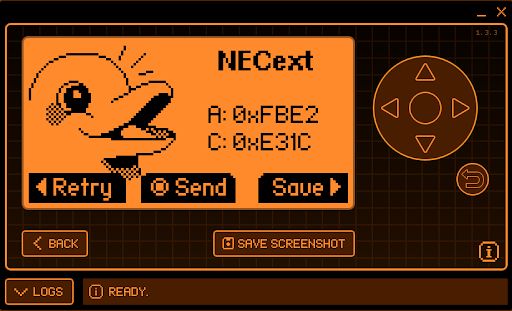
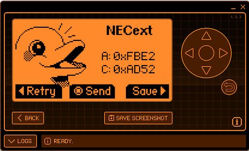
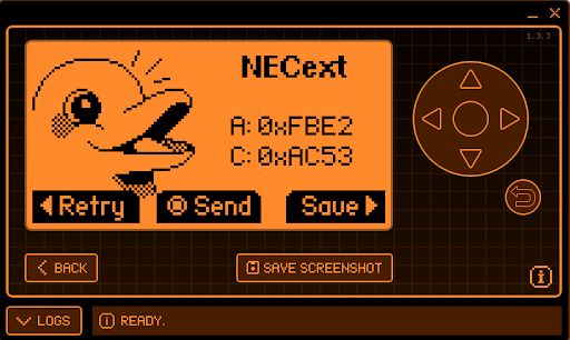
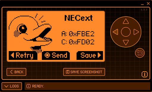
We started by testing with the Flipper Zero, although the OBK would also work well. The remote control uses the NEC. Here's a preview of some basic keys:
Red:
 .
.
Green:
Blue:
White:
 .
.
In OBK, in turn, it is sufficient to set the IRRecv role for the corresponding pin and to make startDriver IR :
Info:MAIN:Time 771, idle 121038/s, free 75448, MQTT 0(48), bWifi 1, secondsWithNoPing 1, socks 2/38
Info:IR:IR MQTT publish IR_NEC 0xFBE2 0x1C 0 (32 bits) took 0ms
Info:IR:IR MQTT publish IR_NEC 0xFBE2 0x1C 1 (0 bits) took 0ms
Info:IR:IR MQTT publish IR_NEC 0xFBE2 0x1C 1 (0 bits) took 0ms
Info:MAIN:Time 772, idle 131402/s, free 75448, MQTT 0(48), bWifi 1, secondsWithNoPing 1, socks 2/38
Info:MAIN:Time 773, idle 133434/s, free 75232, MQTT 0(48), bWifi 1, secondsWithNoPing 1, socks 3/38
Info:MAIN:Time 774, idle 150269/s, free 75448, MQTT 0(48), bWifi 1, secondsWithNoPing 1, socks 2/38
Info:IR:IR MQTT publish IR_NEC 0xFBE2 0x1C 0 (32 bits) took 0ms
Info:IR:IR MQTT publish IR_NEC 0xFBE2 0x1C 1 (0 bits) took 0ms
Info:MAIN:Time 775, idle 137090/s, free 75448, MQTT 0(48), bWifi 1, secondsWithNoPing 1, socks 2/38
Info:MAIN:Time 776, idle 127325/s, free 75448, MQTT 0(48), bWifi 1, secondsWithNoPing 1, socks 2/38
Info:IR:IR MQTT publish IR_NEC 0xFBE2 0x1C 0 (32 bits) took 0ms
Info:IR:IR MQTT publish IR_NEC 0xFBE2 0x1C 1 (0 bits) took 0ms
Info:MAIN:Time 777, idle 127220/s, free 75232, MQTT 0(48), bWifi 1, secondsWithNoPing 1, socks 3/38
Info:IR:IR MQTT publish IR_NEC 0xFBE2 0x1C 0 (32 bits) took 0ms
Info:IR:IR MQTT publish IR_NEC 0xFBE2 0x1C 1 (0 bits) took 0ms
Info:MAIN:Time 778, idle 125833/s, free 75448, MQTT 0(48), bWifi 1, secondsWithNoPing 1, socks 2/38
Info:MAIN:Time 779, idle 123395/s, free 75448, MQTT 0(48), bWifi 1, secondsWithNoPing 1, socks 2/38
Info:IR:IR MQTT publish IR_NEC 0xFBE2 0x1C 0 (32 bits) took 0ms
Info:IR:IR MQTT publish IR_NEC 0xFBE2 0x1C 1 (0 bits) took 0ms
Info:MAIN:Time 780, idle 133632/s, free 75448, MQTT 0(48), bWifi 1, secondsWithNoPing 1, socks 2/38
Info:IR:IR MQTT publish IR_NEC 0xFBE2 0x1C 0 (32 bits) took 0ms
Info:IR:IR MQTT publish IR_NEC 0xFBE2 0x1C 1 (0 bits) took 0ms
Info:MQTT:mqtt_host empty, not starting mqtt
Also works! The IR codes are seen correctly.
This is how you can collect IR codes, then you have to assign actions to them.
According to the documentation:
https://github.com/openshwprojects/OpenBK7231T_App/blob/main/docs/commands.md
and with our video:
we created autoexec.bat:
startDriver IR

//all LED's ON
addEventHandler2 IR_NEC 0xFBE2 0x26 led_enableAll 1
//all LED's OFF
addEventHandler2 IR_NEC 0xFBE2 0x25 led_enableAll 0

//setting RGB
//RED
addEventHandler2 IR_NEC 0xFBE2 0x1C led_basecolor_rgb FF0000
//GREEN
addEventHandler2 IR_NEC 0xFBE2 0x52 led_basecolor_rgb 00FF00
//BLUE
addEventHandler2 IR_NEC 0xFBE2 0x53 led_basecolor_rgb 0000FF
//WHITE
addEventHandler2 IR_NEC 0xFBE2 0x2 led_basecolor_rgb FFFFFF

//setting brightness
addEventHandler2 IR_NEC 0xFBE2 0x5A add_dimmer 5
addEventHandler2 IR_NEC 0xFBE2 0x10 add_dimmer -5
The script controls the IR controller and then adds an IR_NEC event handler where the captured information of the sent commands is entered. The corresponding commands are mapped to commands for the OBK to, for example, set a particular colour or turn the bar on/off.
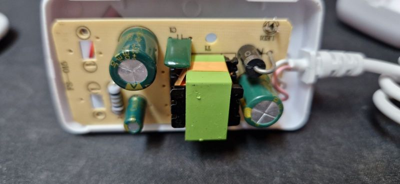
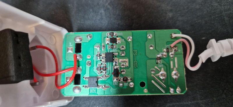
Interior of the power supply .
Again, a glued enclosure. We are looking at:
 .
.
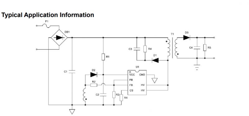
A complete classic. As usual. Simple fuse resistor at the input and integrated flyback controller PSR (Primary Side Regulation). Only an auxiliary winding for the power supply with a rectifying diode and a gasifier (on the second diode and with this green capacitor). On the secondary side a Schottky diode and one capacitor (hopefully low ESR):
 .
.
 .
.
Simply the same as usual.
Summary .
Pretty good kit, but the power supply is budget as usual.
The batch is easy to change, and OpenBeken once uploaded will even embrace the remote control.
There is still a microphone there, but we had no need to run it with a colleague.
We have converted all the strips to Home Assistant and are happy with them.
By the way, there was no LED strip controller on the CBU module on our forum yet. This opens up new possibilities for modifications. One could, for example, connect the WS2812B to the P16 just available on the CBU, but problematic with the CB2S/CB3S (it is not brought out there).
Unfortunately, here too I have to complain a little - this is another product without a physical button. And what, if we lose the phone (and the remote control) we can't switch off the light? Fortunately, with a firmware change this can be easily fixed:
https://www.youtube.com/watch?v=vDh8Y_NDrb4&ab_channel=Elektrodacom
And you can also simply configure, for example, a light switch (also from OBK) to control this bar, but about that another time.
In summary - you can consider such a set-up, with Home Assistant you can certainly get it to work 100% locally.
Cool? Ranking DIY Helpful post? Buy me a coffee.


