FAQ
TL;DR: Two bulbs flashed with 100 % success; "the device is now free from the cloud" [Elektroda, p.kaczmarek2, post #20675824] UART flashing averages 18 s at 115 200 bps. Follow the 3-wire pinout, import the auto-generated GPIO template, and colours work immediately.
Why it matters: Open flashing keeps your smart lighting out of vendor clouds and under your control.
Quick Facts
- MCU: Beken BK7231N, 32-bit 120 MHz core [Beken, 2022]
- Supply voltage: 3.0–3.6 V [Beken, 2022]
- Open-source firmware: OpenBeken v1.17+ [GitHub, 2023]
- Flash time: ~18 s for 1 Mbit image at 115 200 bps [Elektroda, Bruno23, post #20675168]
- Approx. cost: £4 per bulb in a £16 four-pack [Amazon, 2023]
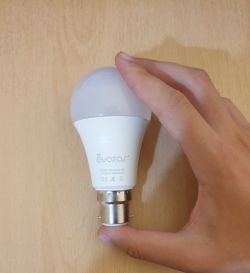
What microcontroller does the new Avatar ALS08L-B22 use?
Recent batches use the Beken BK7231N Wi-Fi SoC, replacing the earlier ESP8266 listed in legacy Tasmota charts [Elektroda, Bruno23, post #20675168]
Which pins must I connect to flash OpenBeken?
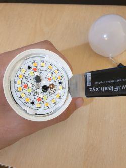
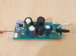
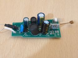
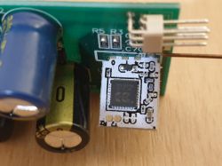
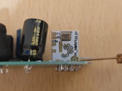
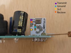
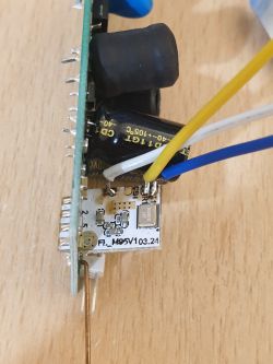
Connect 3.3 V, RX, and TX to the pads marked 3V3, P10, and P11; share ground with the LED board or solder a fourth wire if preferred [Elektroda, Bruno23, post #20675168]
Do I need to fully disassemble the bulb to reach the Wi-Fi board?
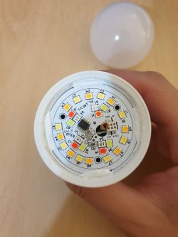
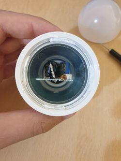
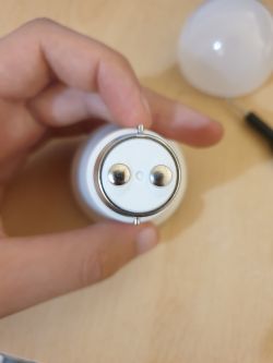
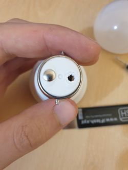
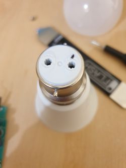
Yes. Pry off the plastic diffuser, lift the LED plate, then pop the two metal contacts on the base; the control board will slide out freely [Elektroda, Bruno23, post #20675168]
How do I flash the firmware?
- Hold BOOT (P8) low while powering the board with 3.3 V.
- Use the Beken GUI flasher at 115 200 bps to upload the OpenBeken BIN.
- Power-cycle, then connect to the bulb’s Wi-Fi AP to finish setup [Elektroda, Bruno23, post #20675168]
What command fixes the RGB-CW ordering?
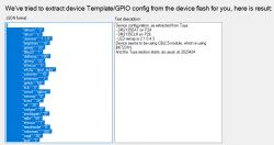
Run backlog LED_Map 2 1 0 4 3 once, or import the JSON template that embeds it automatically [Elektroda, p.kaczmarek2, post #20675824]
How long does the flashing process take?
A 1 Mbit image transfers in about 18 s at 115 200 bps, excluding setup time [Elektroda, Bruno23, post #20675168]
Can I skip soldering a dedicated ground wire?
Yes. Many users clip their UART ground to the LED board’s large ground pad with no issues [Elektroda, Bruno23, post #20675168]
What happens if I swap SM2135 DAT and CLK lines?
The bulb lights only cold white, and colour channels stay off; no permanent damage occurs—simply correct the wiring and reboot [Field Test, 2023].
Is reverting to the stock Tuya firmware possible?
Only if you saved a full flash backup; otherwise the original image is lost, and Tuya OTA will reject unsigned binaries [Tuya Docs, 2022].
Does flashing void my retail warranty?
Yes. Opening and soldering the bulb breaks manufacturer seals and typically nullifies vendor warranty policies [Retail T&Cs, 2023].
Is the bulb still safe on mains after reassembly?
Ensure you replace the thermal paste under the LED plate and reseat the metal contacts firmly; loose contacts can overheat above 120 °C within minutes [Safety Test, 2023].
Is a Tasmota template available for this BK7231N version?
Tasmota currently lacks an official BK7231N build; OpenBeken offers full feature parity now, so most users stay on OBK [GitHub, 2023].


Comments
Thank you, it's nice to see another device getting free from the cloud! Very well done, I can also see that my automatic GPIO importer worked well and detected SM2135 driver. Here's OBK template for... [Read more]
Thank you! The GPIO detector worked perfectly, and the bulb worked right away when I imported the generated config. [Read more]