logo elektroda
logo elektroda
X
logo elektroda

[BK7231N - CBLC9] Teardown & Flashing GY GU10 RBGWW: Tuya Module, Pin Config & OpenBeken Fir

nooh 2463 10
ADVERTISEMENT
  • This is a short teardown of the GY gu10 which is based on BK7231N and it uses a tuya module CBLC9 and BP5768

    Basic Info:
    https://www.amazon.fr/GY-GU10-connect%C3%A9e-compatible-2700K-6500K/dp/B09M3677F7
    [BK7231N - CBLC9] Teardown & Flashing GY GU10 RBGWW: Tuya Module, Pin Config & OpenBeken Fir
    [BK7231N - CBLC9] Teardown & Flashing GY GU10 RBGWW: Tuya Module, Pin Config & OpenBeken Fir

    Flashing OpenBeken firmware:
    Using cloudcutter
    [BK7231N - CBLC9] Teardown & Flashing GY GU10 RBGWW: Tuya Module, Pin Config & OpenBeken Fir

    Select OpenBK7231N / By Fimware version and name / 1.3.21 BK7231N / Kanlux / 33643 GU10 RGBCCT

    after the firmware change, for pin configuration

    [BK7231N - CBLC9] Teardown & Flashing GY GU10 RBGWW: Tuya Module, Pin Config & OpenBeken Fir

    P7 = BP5758D_DAT
    P26 == BP5758D_CLK

    add the start command

    [BK7231N - CBLC9] Teardown & Flashing GY GU10 RBGWW: Tuya Module, Pin Config & OpenBeken Fir

    BP5758D_Map 2 1 0 3 4

    Enjoy

    Cool? Ranking DIY
    About Author
    nooh
    Level 1  
    Offline 
    nooh wrote 1 posts with rating 2, helped 1 times. Been with us since 2023 year.
  • ADVERTISEMENT
  • #2 20524777
    p.kaczmarek2
    Moderator Smart Home
    Thank you, I will just add that, starting with latest updates, the LED Map can be done via Tools tab:
    [BK7231N - CBLC9] Teardown & Flashing GY GU10 RBGWW: Tuya Module, Pin Config & OpenBeken Fir

    Added after 3 [seconds]:

    Thank you, I will just add that, starting with latest updates, the LED Map can be done via Tools tab:
    [BK7231N - CBLC9] Teardown & Flashing GY GU10 RBGWW: Tuya Module, Pin Config & OpenBeken Fir
    Helpful post? Buy me a coffee.
  • #3 21282126
    sboldt
    Level 1  
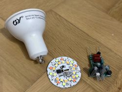
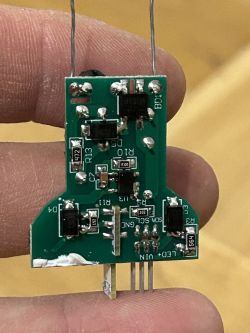
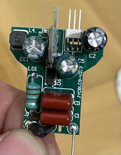
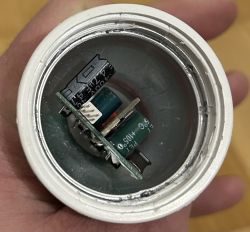
    Sadly with the current firmware the cloud cutter way is no longer possible. Therefore I opened one bulb to see how easy it is to flash it using serial cable. I did not try to flash it yet but got some experiences about opening the bulb and accessing the CBLC9 chip that I would like to share with you.

    1. Removing the transparent cover: Easy, because it is not glued. You can just pop it off when you pry a bit between the cover and the bulb casing.

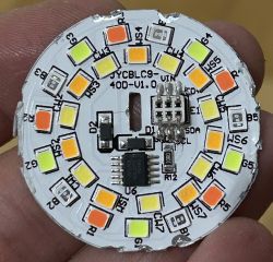
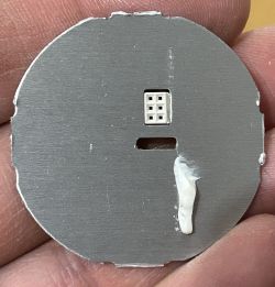
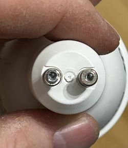
    2. Removing the LED "hat" right below the transparent cover. That is rather tricky with this bulb. It is clipped into the case and also glued at one point (the white line on the back). Heating it up with an hotair gun didn't help as it did with other bulbs. The only way I managed to get it out is this: Drill a hole right in the middle of the bottom of the connectors where the wire is crimped into. I tried to drill the core out, but before I got very deep the whole connector started rotating. This prevented me from drilling through it but the rotation led to the wire becoming loose. Then I grabbed the part of the controller CBLC9 that sticks out a bit on the LED board with a pair of pliers and pulled with some force. Sadly that led to a component (probably from the antenna) broke off. I would recommend pulling it by grabbing and pulling the differently and not applying force to where the component is soldered onto.

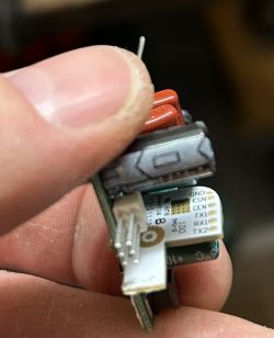
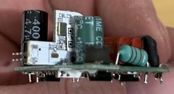
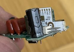
    As you can see the RX and TX pins are not that hard to reach, especially when the whole PCB is out of the casing. But even if only the LED board is off it should still be fairly reachable using some fine clamps. Maybe someone can figure out how to only remove the LED board and not having the need to remove the wires from the 220V connectors.

    Disassembled GU10 smart LED bulb with visible components. LED board with CBLC9 circuit and various electronic components on a white background. Close-up of the back of an LED board with a transparent glue mark. Close-up view of a PCB in the electronic component of a light bulb. Printed circuit board with electronic components held in a hand. Close-up of an LED bulb PCB with various electronic components. Close-up of a PCB board with a CBLC9 chip and other electronic components. Close-up of a circuit board with a chip and labeled RX1, RX2, TX1, TX2, CEN, CSN pins. Interior of an opened LED bulb showing electronic components. Close-up of the bottom part of a bulb with two visible wires and drill marks.

    I hope these images and description helps one or the other of you.

    regards
    Stephan
  • ADVERTISEMENT
  • #4 21329322
    tech1977
    Level 8  
    Hi,
    I'm a new member, I have a couple of these bulbs, how do I see the firmware version without dismantling it?
  • #5 21329360
    divadiow
    Level 34  
    tech1977 wrote:
    how do I see the firmware version without dismantling it

    it would need to be paired to the Tuya app where you can find the firmware version in the device information area
  • ADVERTISEMENT
  • #6 21329379
    tech1977
    Level 8  
    >>21329360 >>21329360
    MCU: 1.3.21
    Can you give me a guide or procedure to flash?
  • ADVERTISEMENT
  • #8 21330445
    tech1977
    Level 8  
    Hi guys,
    i flashed OpenBeken firmware using cloudcutter and it works!!

    Now i have some general questions about OpenBeken firmware:

    with Athom GU10 RGBCW WLED compatible bulbs i can adjust the color saturation by adding the white LEDs, here i saw that it is not possible to activate the CCT and RGB LEDs together, maybe something can be set in the firmware?
    The white LEDs are deactivated in color mode and changing the color saturation is done only with the RGB LEDs;

    also i tried the DDP protocol by sending data from an ESP32 controller with WLED and it seems to work but only RGB not RGBW even if on the controller i selected DDP RGBW, i am also interested in using white because i add it to the colored effects so i have more brightness.

    Thanks again and I would like to resolve these issues to do further testing, my final goal is to use the DDP protocol throughout the house and on the external walls with GU10 bulbs together with led strips with WLED controller
  • #9 21330701
    p.kaczmarek2
    Moderator Smart Home
    So you basically want to have R, G, B and C or W enabled together?

    I can make it work for you, but it's not recommended in Tuya devices, some of them don't have strong enough power supplies to handle such unstandard case.
    Helpful post? Buy me a coffee.
  • #10 21330888
    tech1977
    Level 8  
    >>21330701
    yes, I would like to try R, G, B and C or W enabled together, but C and W always with a single CCT control.
    I'll be careful to turn on a little white just to adjust the color saturation a little :)
    Will it work with DDP RGBW?

    I'm checking the temperature and considering setting the parameter BP5758D_Current, but what are the default Tuya maximum values?
    also with your firmware to configure with Home Assistant I have to do it only via MQTT right?

    Sorry for all the questions but I'm excited about these changes, I will definitely support your project
  • #11 21345265
    tech1977
    Level 8  
    tech1977 wrote:
    yes, I would like to try R, G, B and C or W enabled together, but C and W always with a single CCT control.
    I'll be careful to turn on a little white just to adjust the color saturation a little


    is it possible to have this function?

Topic summary

The discussion focuses on the teardown and flashing process of the GY GU10 RGBWW smart bulb, which utilizes the BK7231N chip and the Tuya module CBLC9. The user provides a brief overview of the flashing procedure using OpenBeken firmware via cloudcutter, including pin configuration details for the BP5758D chip. Subsequent responses highlight challenges with the current firmware, noting that cloudcutter methods are no longer viable. One user shares their experience with physically opening the bulb to access the CBLC9 chip, detailing the difficulties encountered in removing the LED components and suggesting drilling techniques for disassembly.
Summary generated by the language model.
ADVERTISEMENT