Amplifier plus DAB+ filter without compromise
As I have been receiving DAB+ Digital Radio for a long time, I am also struggling with reception efficiency, even though the assumptions of the DAB radio specification (DAB+) were to ensure not only digital quality, but also ensure effective reception even in difficult conditions.
Unfortunately, the assumptions were "slightly" different from reality, as I often travel by car and I have a DAB+ receiver in the car, which means that I know "how it is".
And while the reception of regular VHF radio is not difficult even in mountainous or foothill areas (around Krakow), unfortunately for the reception of DAB+ radio, the first large hill that covers the transmitter quickly causes the signal to disappear. Unfortunately, the operating frequency range (174-230 MHz) means that the range is basically optical and while close (~ 20 km from the transmitter) in built-up areas is rather (but not always) problem-free, the further away the worse.
Another issue is the weak input circuits of DAB receivers, they are as simplified as possible, and the receivers are most often single-chip with zero input filters, which also limits the receiving capacity of the receivers.
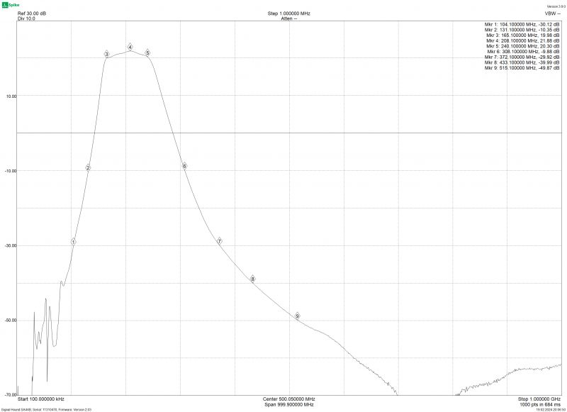
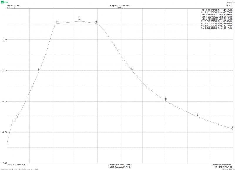
So I assumed the construction of an amplifier for a DAB receiver with an input filter system, the minimum gain of such a system in the entire band is ~20 dB with filtering outside the min. 30 dB.
I didn`t make any compromises here - the elements I used were Mini-Circuits circuits and filters.
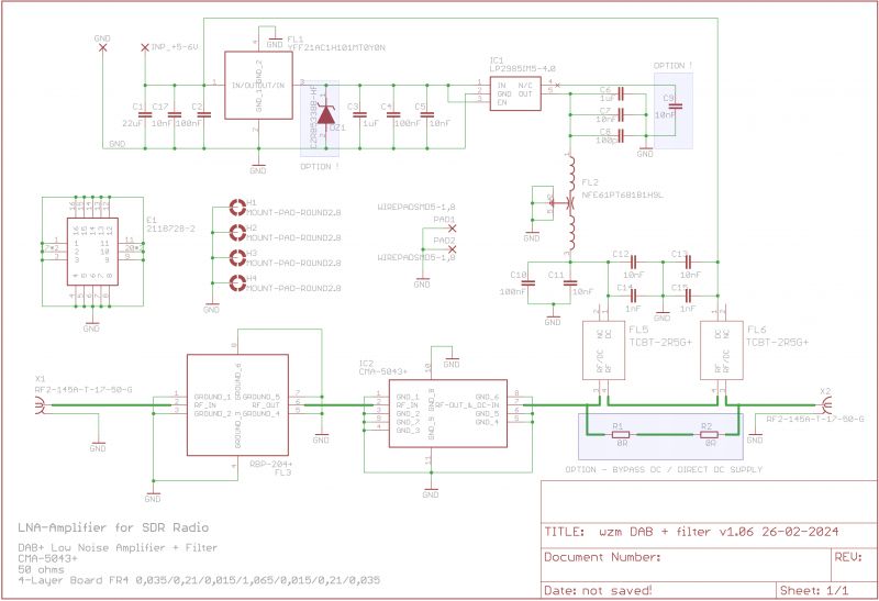
The system used is CMA-5043, and the filter is RBP-204, the system is powered from the output and can be supplied from 5 V to 12 V, and the LP2985 4 V stabilizer system is used, additionally two blocks are used Bias Tee - TCBT-2R5G elements for receiving DC voltage and then applying a stable voltage to the amplifier system.
The system can be directly powered from the antenna output (voltage range 4-5 V) (OPTION 1),
OPTION 2 is an additional capacitor that reduces the self-noise of the LP2985 stabilizer, OPTION 3 is an additional Zener diode that can be used to protect against too high voltage (when using another stabilizer).
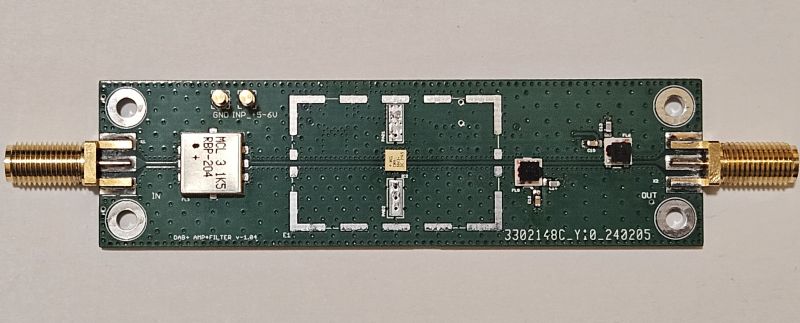
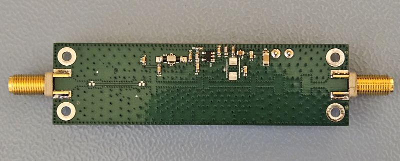
The board was designed as 4-layer (wave impedance).
Diagram:
Printed circuit board in 2 views:


Render view:


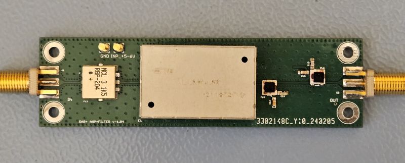
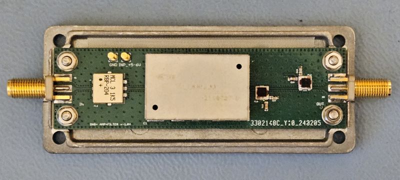
Views of the completed board with installed elements:
Measurement results of the completed system:
In the range up to 1 GHz:
In the range up to 500 MHz:
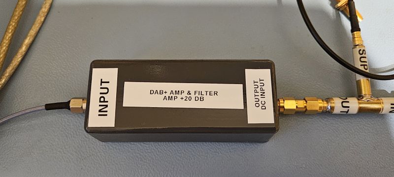
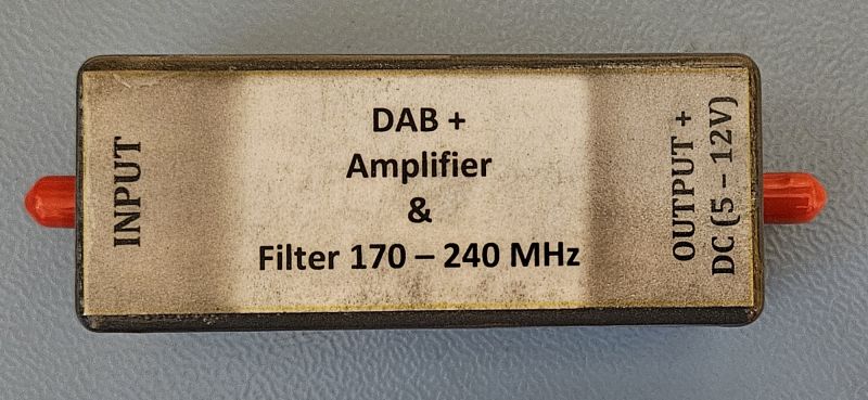
Finally, the amplifier looks like this (the housing was encapsulated by protecting it with varnish):
Unfortunately, the assumptions were "slightly" different from reality, as I often travel by car and I have a DAB+ receiver in the car, which means that I know "how it is".
And while the reception of regular VHF radio is not difficult even in mountainous or foothill areas (around Krakow), unfortunately for the reception of DAB+ radio, the first large hill that covers the transmitter quickly causes the signal to disappear. Unfortunately, the operating frequency range (174-230 MHz) means that the range is basically optical and while close (~ 20 km from the transmitter) in built-up areas is rather (but not always) problem-free, the further away the worse.
Another issue is the weak input circuits of DAB receivers, they are as simplified as possible, and the receivers are most often single-chip with zero input filters, which also limits the receiving capacity of the receivers.
So I assumed the construction of an amplifier for a DAB receiver with an input filter system, the minimum gain of such a system in the entire band is ~20 dB with filtering outside the min. 30 dB.
I didn`t make any compromises here - the elements I used were Mini-Circuits circuits and filters.
The system used is CMA-5043, and the filter is RBP-204, the system is powered from the output and can be supplied from 5 V to 12 V, and the LP2985 4 V stabilizer system is used, additionally two blocks are used Bias Tee - TCBT-2R5G elements for receiving DC voltage and then applying a stable voltage to the amplifier system.
The system can be directly powered from the antenna output (voltage range 4-5 V) (OPTION 1),
OPTION 2 is an additional capacitor that reduces the self-noise of the LP2985 stabilizer, OPTION 3 is an additional Zener diode that can be used to protect against too high voltage (when using another stabilizer).
The board was designed as 4-layer (wave impedance).
Diagram:

Printed circuit board in 2 views:


Render view:


Views of the completed board with installed elements:


Measurement results of the completed system:
In the range up to 1 GHz:

In the range up to 500 MHz:

Finally, the amplifier looks like this (the housing was encapsulated by protecting it with varnish):


Comments
You don`t write anything about the antenna - maybe there is a fault in the antenna installation? The amplifier looks interesting, but the antenna is always the main topic to solve, the amplifier comes... [Read more]
Well, I don`t write anything about the antenna because the antenna has nothing to do with it. The antenna installations are different in the car - this is the original, in the other locations these are... [Read more]
Just because it`s original doesn`t mean it`s ok. Often it is an antenna that is not fully matched (some quarter, too short for FM and too long for DAB), and an amplifier is used. I know that you can... [Read more]
The amplifier is not intended for a car radio, so I mainly use sulfur in the radio :) This is for stationary/field reception testing. FM is surprisingly able to receive on a piece of wire even in "difficult"... [Read more]
And I guess it`s better. Someone will still think about giving up the analogue. [Read more]
With the stations that are placed on the multiplex (at least in my case), it will certainly die. There`s nothing to listen to there. [Read more]
There were ideas to turn off FM, as far as I remember, it was turned off in Norway Link 1 Link 2 [Read more]
Out of curiosity, I would like to ask what influenced the choice of ready-made solutions - especially the filter? From what you show, you have the knowledge and resources to make a bandpass filter yourself. ... [Read more]
If it`s supposed to be an amplifier with a filter for RTL-SDR, I`m not surprised. As for DAB+ reception in the field, it`s unfortunately a lottery. For example, in Chełmno I can currently receive two... [Read more]
And why should I do something when something is ready? I used it (this filter is both easy and not easy to make) The airwaves are full of sources of interference. Using traps for a given frequency makes... [Read more]
I found a table which shows that the signal level for the subscriber sockets (it can be assumed that the signal levels from the receiver`s antenna) for DAB is at least 28µV, and for FM stereo it is at... [Read more]
Sorry, what are you writing about? What subscriber sockets? Moreover, I would like to know what the 28 uV level means in the DAB signal? (I suggest you familiarize yourself with the structure of the... [Read more]
This is the signal level for the subscriber socket - it is something you have in the wall and you connect a tuner to it (in short). This is the minimum signal level required by the DAB+ standard - meters... [Read more]
By the way, what does an FM/DAB tuner look like today? Well, let`s take a look at the tuner for about PLN 2,000 https://obrazki.elektroda.pl/5595594400_1709206720_bigthumb.jpg we also have a specific... [Read more]
DAB, like DVB-T2, has no intermediate states, as in the analog signal - it receives, but there is a bit of noise, or there is no stereo. Here it either receives and decodes, or there is nothing. [Read more]
And that`s a bit of a problem. Even though there was some noise in FM, it just dies here, which is irritating. [Read more]
This is the specificity of the digital signal. This is the direction the world is heading. [Read more]
First tests Kraków QTH: KO00AC02 Reception was trouble-free (other weaker stations) - I omitted local or very strong stations. MUX Świety Krzyż 215.072 MHz (ERP 10 kW) - Emitel MUX Prehyba - Szczawnica... [Read more]
And what signal levels? What antenna? In the car? [Read more]