logo elektroda
logo elektroda
X
logo elektroda

Simple AM/FM radio - Lowry - CD2003GP and D2822A - SC3610D connectable

p.kaczmarek2 2427 26
ADVERTISEMENT
Treść została przetłumaczona polish » english Zobacz oryginalną wersję tematu
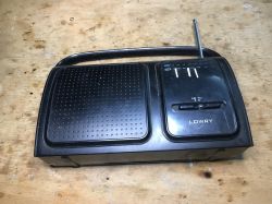
  • Black LOWRY portable radio with an extended antenna on a wooden surface. .
    Some time ago I showed the Fonics FN-105 radio, which turned out to be based on the CD7613CP chip, a so-called 'one-chip radio'. It even had an audio amplifier in it. Now it is time for another similar radio, but this time built slightly differently. We will look inside and analyse the PCB.

    Previous related topic in the series: Fonics FN-105 - CD7613CP .

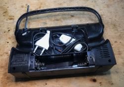
    This radio also belongs to a friend from the allotments and it too has this distinctive modification with a switch on the cable. The friend must like these switches. You can get quite a surprise when you open the battery slot:
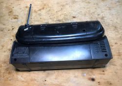
    A black, rectangular portable radio on a wooden surface, viewed from the top and back; an extended telescopic antenna is visible. .
    Who would have expected:
    Open battery compartment of an old radio with a power cord and a switch stored inside. .
    Removing the case, inside is the speaker, one PCB and the mains transformer:
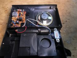
    Inside of an opened transistor radio showing a PCB, speaker, and transformer. .
    Interestingly, the transformer has a built-in thermal fuse:
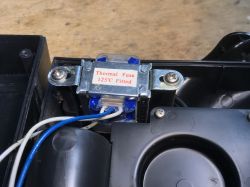
    Mains transformer installed in a plastic enclosure, featuring a visible 125°C thermal fuse. .
    I wonder how effective it is.
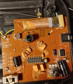
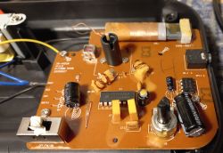
    Now the PCB itself, the layout is even simpler than before, apart from the obvious presence of a ferrite antenna and an adjustable capacitor used for tuning, here we have a headphone socket, a couple of properly protected air-core coils and this time two chips: CD2003GP and D2822A
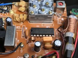
    Close-up of a radio PCB showing a CD2003GP IC, coils, capacitors, and other electronic components. .
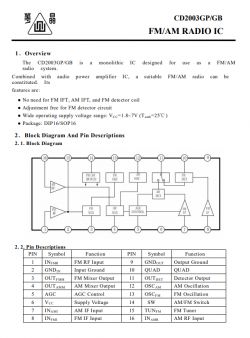
    Catalogue note:
    Section of the CD2003GP/GB datasheet with block diagram and pinout table. .
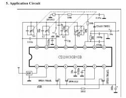
    Example application diagram:
    Application circuit diagram of CD2003GP/GB chip with passive and active component connections. .
    I think I even know this schematic from somewhere, haven't I done a DIY like this before? But let's not forget the D2822A amplifier (looks similar TDA2822M?):
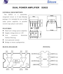
    Fragment of the D2822 audio amplifier datasheet with block diagram, pinout, and package dimensions. .
    This die can be used in both mono and stereo applications:
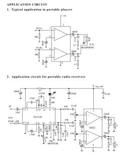
    Two application circuit diagrams for the D2822A amplifier: the first for a portable player, the second for a radio receiver. .
    Another look at the underside of the PCB - there are some SMD components here, this explains why the board is slightly smaller than I would have expected. The rectifier diodes are also surface mounted.
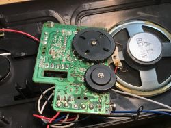
    A circuit board with two black gears and a visible 8Ω speaker inside an opened radio case. .
    By the way, the diodes are three and have small ceramic capacitors in parallel.... one of them probably protects the batteries, so either from the transformer there must be a single pole rectifier or the transformer is tapped?
    Judging by the fact that only two of the diodes have a capacitor, I would bet that there is a transformer with a split secondary winding....
    And I think that's it - there's one more photo of the whole PCB left:
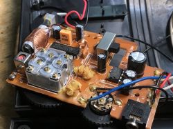
    Radio PCB with electronic components, visible coils, capacitors, CD2003GP chip, and headphone jack. .

    Summary .
    This is interesting, the previously described Fonics FN-105 was based on a single chip, the CD7613CP, and had no SMD components, here they have introduced a bit of SMD already, but the amplifier and radio circuit are separate.
    The CD2003 used here is a classic, and I have seen DIY projects/kits to assemble on it, including even a project with a frequency display:
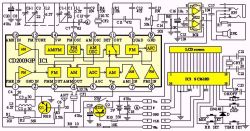
    Block diagram of a radio circuit with CD2003GP, 2822, and SC3610D integrated circuits and labeled connections. .
    Here the SC3610D is used in conjunction with the CD2003. If you are interested, you can look for this kit to buy online, although I would rather be tempted to DIY modify a ready-made radio.... maybe it would be possible to buy an SC3610D, only probably worse in terms of cost, all of which would make it just art for art's sake.
    Alternatively, you could always just buy a ready-made FM Radio Kit and put it together, maybe some readers have played around like that? From what I remember, I once assembled a simple radio myself, also on a ready-made IC, only now I can't remember if it was a CD2003 or another one...

    Cool? Ranking DIY
    Helpful post? Buy me a coffee.
    About Author
    p.kaczmarek2
    Moderator Smart Home
    Offline 
    p.kaczmarek2 wrote 11811 posts with rating 9921, helped 563 times. Been with us since 2014 year.
  • ADVERTISEMENT
  • #2 20693942
    acctr
    Level 38  
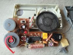
    This time you've come across better grade equipment. On the board you can see two ceramic filters and a resonator. These contribute to the better selectivity of the radio.
    Transformer with split winding (two white and middle blue).
    Thermal fuses are quite effective in such traps, I have had a few pieces of equipment where they have worked after a short circuit and heat up.
    Helpful post? Buy me a coffee.
  • #3 20694022
    TechEkspert
    Editor
    I was always puzzled by those sponges in the air coils that were barely saturated with paraffin.

    Nowadays FM UKF and DAB+ have taken over radio broadcasting in Poland, long wave broadcasts I, there used to be ideas for local medium wave radio stations however I don't know if this works?

    I am curious about your opinion on the PRI receiver project I once came across in EP
    https://ep.com.pl/files/2958.pdf
    https://ep.com.pl/files/2989.pdf
    It differs from typical simple receivers with a resonant circuit on a ferrite antenna and a few transistors,
    contains an NE612 which I associate as a mixer in FM designs,
    what do you think, could such a receiver cope better with the interference generated by pulse converters?
  • ADVERTISEMENT
  • #4 20694554
    398216 Usunięty
    Level 43  
    TechEkspert wrote:
    I've always been puzzled by those sponges in air coils that were barely saturated with paraffin.
    The sponge served as a kind of "filler" - thanks to it, less stearin(paraffin/wax) could be used (depends on the stage/year of production) and it also held the sealant inside the coil. This made the coil much more mechanically stable - it did not change inductance due to shocks. A similar patent was used to immobilise ceramic tuned filters. The flooding ensures stabilisation of the core and at the same time the setting can be changed if necessary. You just have to remember to improve the core stabilisation with a drop of stearin from a candle after tuning.

    As for the themed radio - you can see the newer technology but it doesn't change the class of the equipment - a typical 'kitchen' radio for buzzing in the background of daily activities. For listening to music, it is unsuitable for the same reason as the previous one - the cheapest loudspeaker or, in fact, an imitation of a loudspeaker....

    On the other hand, the designer has shown here an interesting way of hiding the handle in the housing. After folding it becomes almost invisible... ;)
  • #5 20694775
    bratHanki
    Level 38  
    About 10 years ago, when "Everything's 3 zloty each" except what's five 😉 in the shops, you could buy various models of miniature UKF FM receivers that searched for stations by scanning the band up and down. Once one I came across a receiver that allowed manual tuning . At its heart was the SP2003 chip .
  • #6 20694982
    Olkus
    Level 32  
    I've come across the CD2003 a couple of times and even have one (from the outlet). Quite popular in Chinese radios.

    Greetings,
    A.
  • #7 20695116
    bratHanki
    Level 38  
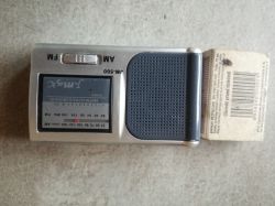
    A small silver Jmax JM-500 portable radio is placed next to a box of matches on a light surface. Interior of an old portable radio showing the circuit board, speaker, and electronic components. .
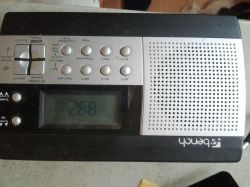
    This is what the first one looks like and the second is a Bench from Lidl, D, ¶, K, UKF waves. Also for 2003.
    Bench portable radio from Lidl with LCD display and silver buttons. .
  • #8 20695198
    p.kaczmarek2
    Moderator Smart Home
    TechEkspert wrote:
    .
    I am curious to hear your opinion on the PRI receiver design I once came across in EP
    https://ep.com.pl/files/2958.pdf
    https://ep.com.pl/files/2989.pdf
    It differs from typical simple receivers with a resonant circuit on a ferrite antenna and a few transistors,
    It contains an NE612 which I associate as a mixer in FM designs,
    .
    I have a couple of NE612's from the cast-off, I think I even described their recovery in one of my disassemblies of an old SAT tuner. Interestingly I also have a TDA2030, UA741 I think. Maybe in my spare time I'll be tempted to try to collect the remaining components and put this together.
    Helpful post? Buy me a coffee.
  • ADVERTISEMENT
  • #9 20695304
    bratHanki
    Level 38  
    Why is the pass band of this receiver 10 kHz when the audio bandwidth is anyway limited to max. 4.5 kHz due to the 9kHz raster?
  • #10 20696290
    acctr
    Level 38  
    TechEkspert wrote:
    I am curious about your opinion on the PRI receiver project I once came across in EP
    https://ep.com.pl/files/2958.pdf
    https://ep.com.pl/files/2989.pdf
    It differs from typical simple receivers with a resonant circuit on a ferrite antenna and a few transistors,
    it contains an NE612 which I associate as a mixer in FM designs,
    what do you think, could such a receiver cope better with the interference generated by pulse converters?
    .
    I would approach this design with caution, there are a lot of coils, 7x7 inductive filters produced back in communist times that are now hard to acquire.
    There is no resonator or ceramic filter, including the easy to get and cheap 456 kHz, instead an LC filter.

    Total immunity from interference on this band is hard to achieve with a ferrite antenna, it depends on the interference spectrum, distance and direction of the ferrite antenna.
    I think there are many other proven AM radio designs with conversion, including on TCA440 chips.
    Helpful post? Buy me a coffee.
  • #11 20696321
    TechEkspert
    Editor
    @p.kaczmarek2 great!
    I would rather dispense with the UA741 in favour of newer versions of the operational amplifier,
    I used NE612 in an FM receiver on 2m and it worked fine,
    You can possibly resign from TDA 2020 in favour of active speakers,
    you can use a universal board or assembly Manhattan .

    With a ferrite antenna there may be a problem, you need a rod, the author does not give the number of turns only the inductance so what remains is an inductance meter, knowledge of the Al of the core or a wavemeter.

    Germanium diodes are another take and 7x7 circuits 105, 104, 116.

    I wonder if such a receiver could be used for listening to e.g. DGPS fix signals from Rozewie https://odtur.pl/atrakcje/rozewie-dgps-transmitter-na-rozewiu-40925.html and listening tests of other radio beacons, becons and AM radio stations http://web.archive.org/web/20100110104328/http://www.mwlist.org/mwlist_quick_and_easy.php
    http://sq8nzf.blogspot.com/2011/03/nasuchy-stacji-dugofalowych.html

    There are also medium-wave emissions but this is already a rod antenna?
    http://radiopolska.pl/wykaz/ampolska.php

    For VLF and e.g. DCF reception it's probably already SDR receivers including Web SDR to check propagation.

    @acctr it was the lack of a filter that drew my attention, 7x7 circuits can still be got e.g. on allegro, in online shops however they are stock.
    There used to be larger sized filters (taller and wider) in the old RTV, they are probably completely out of stock now.
    Can you give us a schematic of the design on the TCA440?
  • #12 20696327
    Olkus
    Level 32  
    TechEkspert wrote:
    Germanium diodes are another catch and 7x7 circuits 105, 104, 116.


    No exaggeration, you can obtain from dismantling some radio, you can even find with a bit of luck in a dumpster ;) I in any case probably have such filters, diodes different.

    Greetings,
    A.
  • #13 20850818
    kristof_61
    Level 11  
    A neighbour also threw me a "Sencor SRD 210B" radio on CD 2003 and TDA 2822 chips. The radio is humming, no FM or AM reception.
    Power supply from 3 x R14 batteries, i.e. 4.5V, and 9.7V from the power supply! Behind trafo on desoldered wires 7,9V .
    The amplifier is in working order so I guess the trafo and CD 2003 hit.
    Is it possible to buy such a circuit?
  • #14 20854300
    Olkus
    Level 32  
    kristof_61 wrote:
    Is it possible to buy such a deal?


    You can, they are on Aliexpress. There are still chips left from disassembly if you don't want to buy there, find a donor or someone who has one. I have one, but I don't know if it's working.
    Another issue is the viability of repairing this radio....

    Regards,
    A.
  • #15 20854768
    kristof_61
    Level 11  
    There are 2 offers on the web for about £10 each + postage. In my shop they demand 32 zł. What about the voltage from the 9.7V power supply? The power supply parameters for this circuit are 1.8-7V.
  • #16 20855244
    bratHanki
    Level 38  
    And this is probably the cause. My radio from Lidl has a 6V power supply at idle.
  • #17 20855248
    Olkus
    Level 32  
    kristof_61 wrote:
    And what about the voltage from the 9.7V power supply? The power supply parameters for this circuit are 1.8-7V
    .

    There is no voltage stabiliser or anything to lower this voltage?

    Greetings,
    A.
  • #18 20855299
    kristof_61
    Level 11  
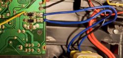
    There is no stabiliser (you will have to insert one). There are only two diodes in parallel ( track side) and a capacitor in the power supply.
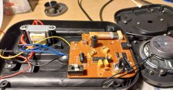
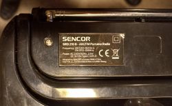
    Printed circuit board with electronic components, including capacitors and diodes. Close-up of a circuit board with electronic components like diodes and capacitors. Open electronic device with visible circuit board and electronic components. Nameplate of the SENCOR SRD 210 B portable radio with technical information. Nameplate of the SENCOR SRD 210 B portable radio with technical information. .
  • #19 20856723
    Olkus
    Level 32  
    Capacitors worth reviewing
    Are you sure these diodes are in parallel? I would rather bet on a two diode rectifier here.

    Regards,
    A.
  • #21 20859621
    kristof_61
    Level 11  
    I wrote that two diodes in parallel. Image of a circuit board with two diodes connected in parallel, using wires in different colors. .
  • ADVERTISEMENT
  • #23 20859911
    398216 Usunięty
    Level 43  
    kristof_61 wrote:
    I wrote that two diodes in parallel.
    You don't know what a parallel connection looks like.
    This is a rectifier circuit using two secondary windings - it needs two diodes.
  • #24 20860017
    bratHanki
    Level 38  
    Maybe not so much two secondary windings as one with a tapping in the middle. Layout-wise, it's two single-voltage rectifiers, each operating in a different half-period.
  • #25 20860246
    398216 Usunięty
    Level 43  
    bratHanki wrote:
    Maybe not so much two secondary windings as one with a tapping in the middle.
    How this is wound is a secondary matter anyway, we have two windings whose centre is connected to earth. And whether two or one with a tapping is a technical matter of the winding itself.

    As a practitioner (because I've wound THOUSANDS of transformers in my life) I can say that technically the "middle" from the "tapping" differs only in where the start of the second winding is shorted to the end of the first. In the case of the taps, this is done just at or on the winding itself, in the other it is done outside the transformer winding.
  • #26 20860267
    bratHanki
    Level 38  
    Oy, I was also turned on by carburettors. To this day I still have a DIY winder with an electromechanical meter from a telephone exchange.
  • #27 20860408
    398216 Usunięty
    Level 43  
    bratHanki wrote:
    I too have been screwed over with carbs.
    You know how it is yourself. Let's end this OT before someone reports....

Topic summary

The discussion analyzes a simple AM/FM radio based on the Lowry CD2003GP and TDA2822A chips, with a focus on its PCB design, components, and power supply issues. The radio features ceramic filters, a resonator, and a transformer with split winding, contributing to improved selectivity. Mechanical stabilization of air coils using paraffin-soaked sponges is explained as a method to maintain inductance stability. The CD2003 chip is noted as common in inexpensive Chinese radios, with references to similar models like the Fonics FN-105 (CD7613CP) and Lidl radios using the same chip. Power supply concerns arise due to the radio being powered by 3x R14 batteries (4.5V) or an external 9.7V source, exceeding the recommended 1.8-7V range, causing humming and reception failure. The power supply uses a transformer with a center-tapped secondary winding and a two-diode rectifier without voltage stabilization, requiring modification for stable operation. Alternative components such as NE612 mixers and TDA2030 amplifiers are mentioned for potential DIY projects. The discussion also touches on the difficulty of achieving interference immunity with ferrite antennas and the scarcity of certain inductive filters from older designs. Overall, the radio is characterized as a basic "kitchen" model suitable for background use rather than high-fidelity listening.
Summary generated by the language model.
ADVERTISEMENT