As I have been receiving DAB+ Digital Radio for a long time, I am also struggling with reception efficiency, even though the assumptions of the DAB radio specification (DAB+) were to ensure not only digital quality, but also ensure effective reception even in difficult conditions.
Unfortunately, the assumptions were "slightly" different from reality, as I often travel by car and I have a DAB+ receiver in the car, which means that I know "how it is".
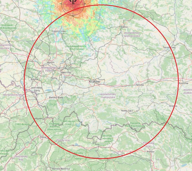
And while the reception of regular VHF radio is not difficult even in mountainous or foothill areas (around Krakow), unfortunately for the reception of DAB+ radio, the first large hill that covers the transmitter quickly causes the signal to disappear. Unfortunately, the operating frequency range (174-230 MHz) means that the range is basically optical and while close (~ 20 km from the transmitter) in built-up areas is rather (but not always) problem-free, the further away the worse.
Another issue is the weak input circuits of DAB receivers, they are as simplified as possible, and the receivers are most often single-chip with zero input filters, which also limits the receiving capacity of the receivers.
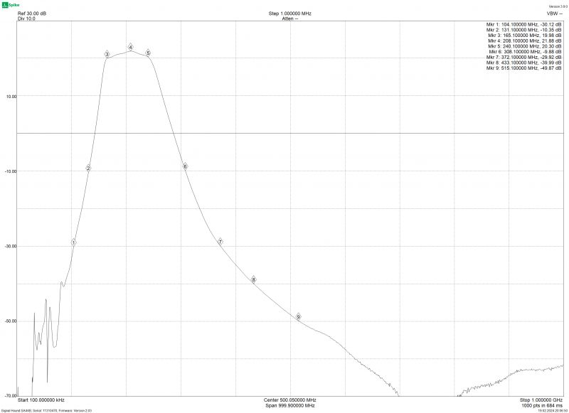
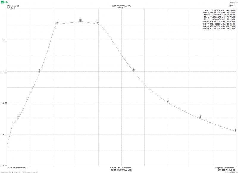
So I assumed the construction of an amplifier for a DAB receiver with an input filter system, the minimum gain of such a system in the entire band is ~20 dB with filtering outside the min. 30 dB.
I didn`t make any compromises here - the elements I used were Mini-Circuits circuits and filters.
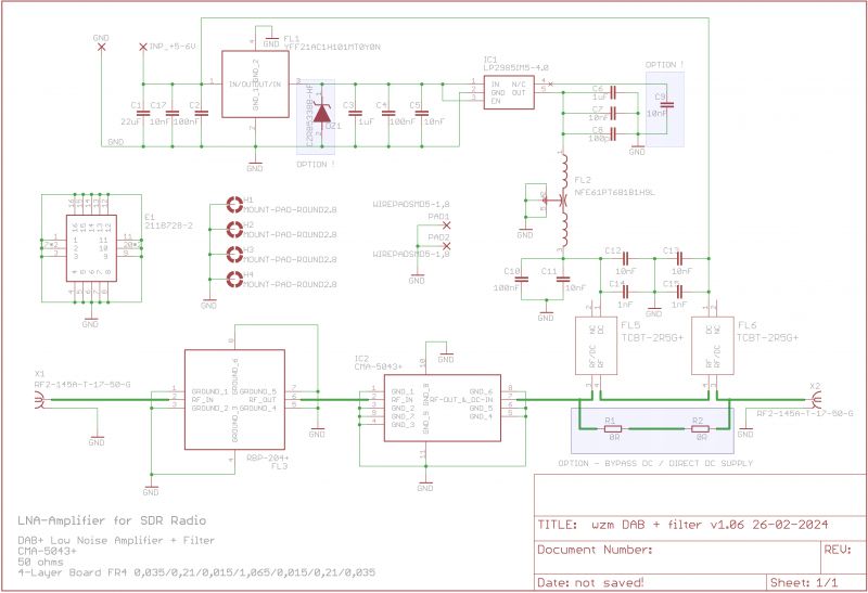
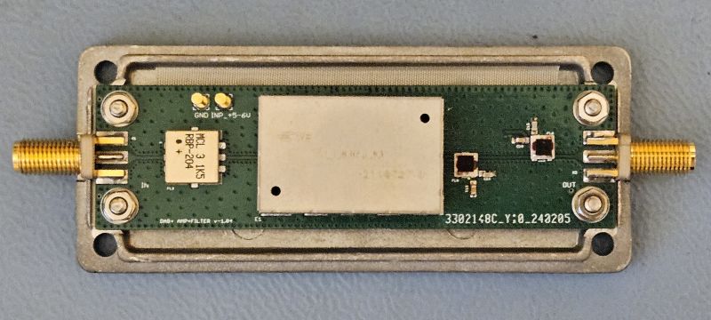
The system used is CMA-5043, and the filter is RBP-204, the system is powered from the output and can be supplied from 5 V to 12 V, and the LP2985 4 V stabilizer system is used, additionally two blocks are used Bias Tee - TCBT-2R5G elements for receiving DC voltage and then applying a stable voltage to the amplifier system.
The system can be directly powered from the antenna output (voltage range 4-5 V) (OPTION 1),
OPTION 2 is an additional capacitor that reduces the self-noise of the LP2985 stabilizer, OPTION 3 is an additional Zener diode that can be used to protect against too high voltage (when using another stabilizer).
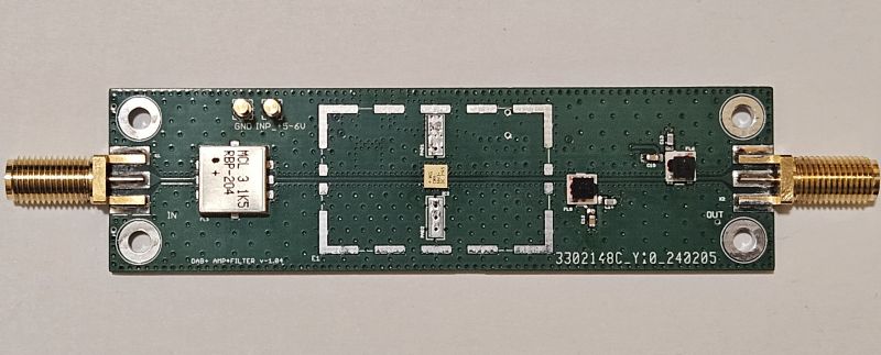
The board was designed as 4-layer (wave impedance).
Diagram:
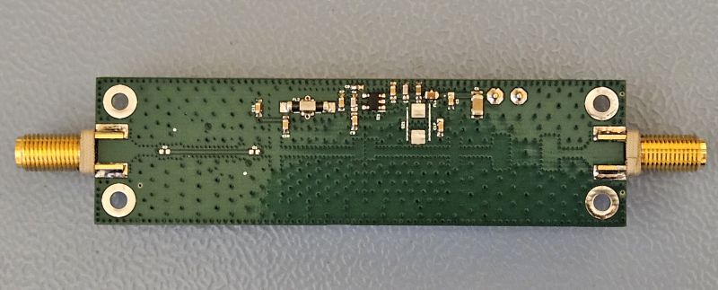
Printed circuit board in 2 views:


Render view:


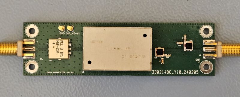
Views of the completed board with installed elements:
Measurement results of the completed system:
In the range up to 1 GHz:
In the range up to 500 MHz:
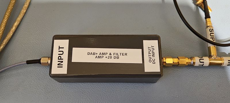
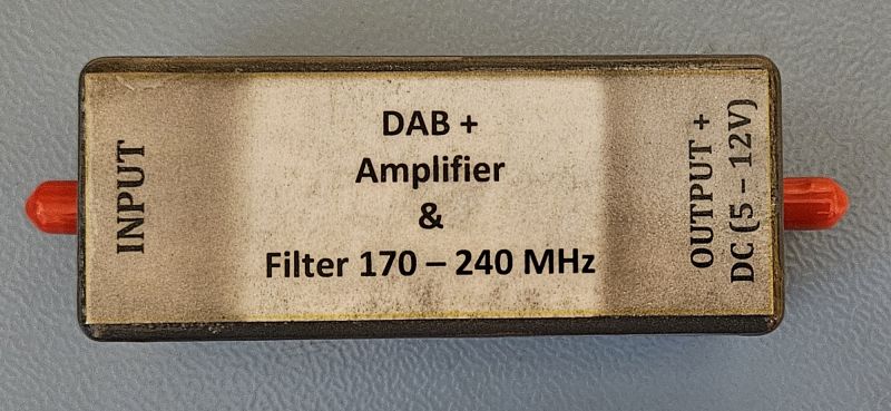
Finally, the amplifier looks like this (the housing was encapsulated by protecting it with varnish):
Unfortunately, the assumptions were "slightly" different from reality, as I often travel by car and I have a DAB+ receiver in the car, which means that I know "how it is".
And while the reception of regular VHF radio is not difficult even in mountainous or foothill areas (around Krakow), unfortunately for the reception of DAB+ radio, the first large hill that covers the transmitter quickly causes the signal to disappear. Unfortunately, the operating frequency range (174-230 MHz) means that the range is basically optical and while close (~ 20 km from the transmitter) in built-up areas is rather (but not always) problem-free, the further away the worse.
Another issue is the weak input circuits of DAB receivers, they are as simplified as possible, and the receivers are most often single-chip with zero input filters, which also limits the receiving capacity of the receivers.
So I assumed the construction of an amplifier for a DAB receiver with an input filter system, the minimum gain of such a system in the entire band is ~20 dB with filtering outside the min. 30 dB.
I didn`t make any compromises here - the elements I used were Mini-Circuits circuits and filters.
The system used is CMA-5043, and the filter is RBP-204, the system is powered from the output and can be supplied from 5 V to 12 V, and the LP2985 4 V stabilizer system is used, additionally two blocks are used Bias Tee - TCBT-2R5G elements for receiving DC voltage and then applying a stable voltage to the amplifier system.
The system can be directly powered from the antenna output (voltage range 4-5 V) (OPTION 1),
OPTION 2 is an additional capacitor that reduces the self-noise of the LP2985 stabilizer, OPTION 3 is an additional Zener diode that can be used to protect against too high voltage (when using another stabilizer).
The board was designed as 4-layer (wave impedance).
Diagram:

Printed circuit board in 2 views:


Render view:


Views of the completed board with installed elements:


Measurement results of the completed system:
In the range up to 1 GHz:

In the range up to 500 MHz:

Finally, the amplifier looks like this (the housing was encapsulated by protecting it with varnish):

Cool? Ranking DIY


