Analogue cell sealing machine
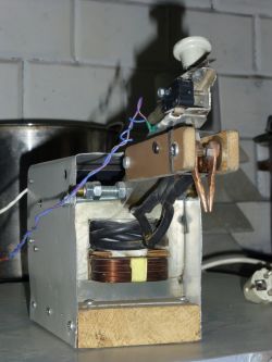 .
.
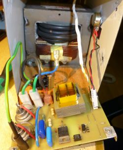
I built a welding machine a few years ago, it was mainly to be used to weld cells into packages. I have a lot of cast-off components, so I'm trying to put at least some of them to some use. Unfortunately this is going with increasing resistance, but that's another topic. So the result is a rather unusual, processorless circuit, altogether simple and cheap, but not lacking in important features. Many welding machine controllers have a disadvantage, despite a stable pulse time, there is no control of the moment when the transformer is connected to the mains, and in the mains, as it is in the mains, the voltage changes all the time. As a result, the portion of energy supplied to the welding spot varies, which can result in burning out the cell or in too weak a weld, as well as overloading the network and tripping the protections. With this in mind, this design was developed:
 .
.
Unfortunately, as it turned out after commissioning, there was a welding time instability, burning out one in 20-30 cells. A ghastly occurrence, fortunately nothing exploded, but you had to pry this burnt cell out of the pack, so overall a big bummer. I tried to find the cause of this instability, modified something there, but it didn't get much better until I finally put the circuit away for lack of time. I occasionally used this welder, with small packets the job usually worked.
Quite recently the need arose to weld a larger packet, I decided to redo the whole controller at the same time.
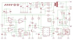
A schematic was created:
 .
.
Maybe it will be useful for someone, also a simple chip without a processor, whether this is a disadvantage or an advantage I will leave to the readers to choose.
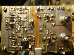
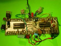
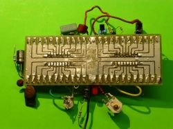
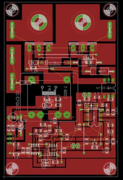
Untreated board, specially designed for my CNC woodworker. Simple copper layer cuts, significant milling inaccuracy allowed, easy post processing.
 .
.
The new arrangement worked well, I welded the package, almost 300 good welds
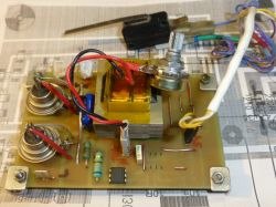
in a row, except that... wanting to speed up the work, the driver was still in spider form, I made the board later. After fitting the new board, I did a few test welds, and it seems to work just as well, which is not at all obvious. Those who know know that spiders can work sensationally, and it is only the making of the plate that spoils the effect.
How it works.
The power circuit consists of a 10-20V 2W transformer, a single-pole rectifier, a single-transistor voltage limiter-stabiliser feeding the circuit. The AC voltage from the transformer via the divider goes to the phase shifter IC3A and further to the comparators that detect the zero crossing, Zero in this circuit is half the supply voltage. The phase shifter is there to be able to hit the peak of the sine wave, which is when there is the least current surge when switching on the high-power tray. Is this successful? Experiments show that this surge can indeed be reduced by adjusting the phase with potentiometer R25. A shifted zero is detected which indicates the peak of the sine wave. A pulse at the peak of the mains voltage appears at the output of the comparators. This signal via the S microstep triggers the LM555 timing circuit. Then it is typical, the optotriac switches on the thyristors, I wanted to use what I have, so here sit the Russian KY202h, but if I burn them all, you can of course insert other newer ones, the board is quite universal.
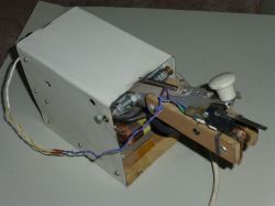
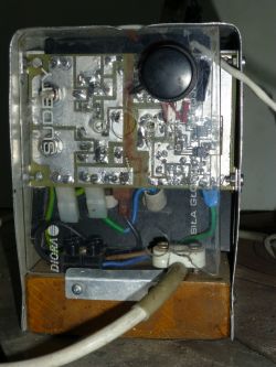
Power trafo standard from microwave, 4 coils I think 16mm, long time ago I wound it I don't remember exactly.
 .
.
Spider testing platform.
 .
.


Comments
Isn't it simpler to time 1/4 of a period from going through "0" which should work out very close to max ? [Read more]
Metering in such a system would be done on some RC anyway. As for the welders, the industrial ones support regulation of time (number of grid periods) and phase angle. Plus some ramping, repetition and... [Read more]
According to the phase shift of current and voltage (the ULICU CIUL or LUIC principle), the voltage precedes the current in the coil by 90 degrees. Including a large transformer ideal at the peak of the... [Read more]
Brave design, yes without a processor hmm. Out of curiosity why the choice without a processor, advantages/disadvantages? Do you perhaps know what caused the instability of the previous solution? Any... [Read more]
@jewishmakaron does this apply to a transient such as switching on? After all, if you switch on at zero, no current will flow (and according to the principle it should automatically generate current). I... [Read more]
. Does the phase shifter do something else? Wrong, the offset between current and voltage is not relevant here, but if anything it is the offset between voltage and magnetic flux. In the case... [Read more]
@acctr so in theory it should matter at what point the trafo was switched off previously ? Was it in quotes "magnetised to N or S" ? [Read more]
. Yes, it matters in practice too and that's where the impulse comes from. But switching on at the peak of the sine ensures that the core does not become saturated. Roughly speaking, it looks like this:... [Read more]
So a better solution would be to switch on the secondary rather than the primary.... , but currents..fact.... [Read more]
Super project! I'm delighted that there are still some hobbyists who can create something practical from scratch, and without a microcontroller. I'll have a look at the schematic when I have a moment. It... [Read more]
. I appreciate with what ease you have managed to explain this :) . If the time during which the flux increases is so important, why not turn on the transformer e.g. 2 milliseconds before going through... [Read more]
. Because this is closer to zero and the risk of core saturation increases. The peak of the sine, at least the 'real' one, is the same distance from the 'left' zero transition and the 'right' one, so... [Read more]
A phase shifter as the name suggests shifts the phase - except that a timer may be more precise here at a lower cost. [Read more]
. If it's possible to achieve the intended functionality by combining a dozen or so simple components, then I guess it's worth taking advantage. Maybe it's out of habit, my adventure with programming... [Read more]
Bottom line. What kind of thyristors should these be, i.e. for what anode current? I can see that a triac is unlikely to replace this. [Read more]
This is about something else. I can't remember with details, but the issue breaks down into differential equations, the principle of continuity of current, the dphi/dt relationship etc. At start-up there... [Read more]
I was intrigued by the handle. A very ingenious solution, a total gimela ;-) . You have used copper wire, of some thickness.... I see that it's vaulted at one end, with the other ground down. How long... [Read more]
. The ones I've inserted have a max of 10A/400V, although in pulse they can probably handle a lot more, so far I haven't burned any. Maybe with a thicker winding there would be a problem. This arrangement... [Read more]
Super project, I will try to copy in the near future. How much 16mm cord so roughly needed to make 5 or 6 coils on a microwave core????? [Read more]