logo elektroda
logo elektroda
X
logo elektroda

Cell welding machine on Chinese DIY driver

kulek855 52818 22
ADVERTISEMENT
Treść została przetłumaczona polish » english Zobacz oryginalną wersję tematu
  • Hello
    I would like to present for evaluation, possibly to indicate errors and defects of my cell welding machine.

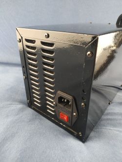
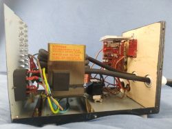
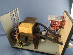
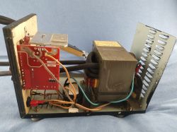
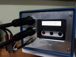
    I do not have access to professional tools, so the housing looks like it looks. It is made of metal sheets left over from a microwave oven, the front part is made of plywood because of easier processing.

    What should be changed in it:
    - convert the cable from 25 mm2 to 35 mm2
    - press the ring terminals with a hydraulic press
    - replace aluminum elements with copper ones in the handle with electrodes

    Initial parameters:
    1300 W transformer
    Secondary winding cross-section 25 mm2
    The voltage of the secondary winding is 3.3 V
    Short-circuit current on the secondary winding 750 A (the meter has a scale of up to 600 A)
    The 40 A driver and electrodes were purchased on aliexpress.

    Current parameters:
    Secondary winding voltage 5V
    Short circuit current on the secondary 910 A


    A video showing the production of the welding machine:


    Photos of the welding machine:
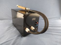
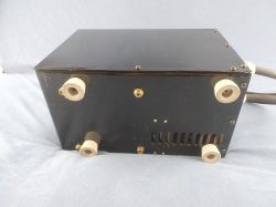
    Homemade spot welder with a metal casing and cables. Rear panel of a spot welder with a switch and ventilation holes Amateur-built cell welder enclosure.

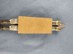
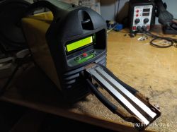
    To make the handle of the welding machine, I used aluminum flat bars, dedicated welding electrodes, springs, screws, OSB and plastic.
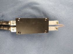
    Handle of a cell welder with aluminum components and copper electrodes on a blue fabric background. Homemade welding machine handle made from wooden board, cables, and metal components.

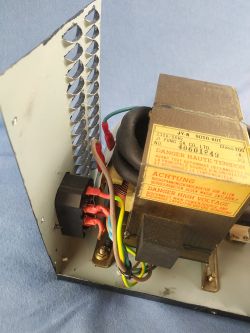
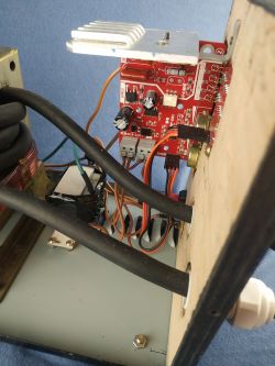
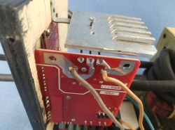
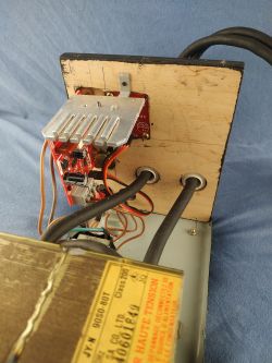
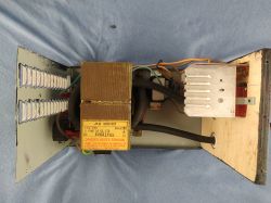
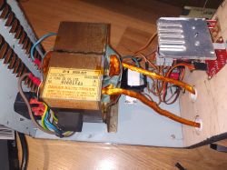
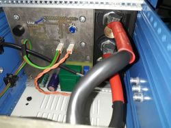
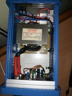
    The inside of the welding machine
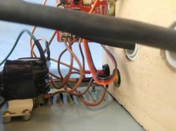
    Interior of a homemade welder made from microwave oven sheet metal. Interior of a homemade welding machine made from metal sheets and plywood. Interior of a DIY spot welder with visible wires and components. Interior of a homemade spot welder made from a transformer and electronic components. Interior of a homemade welder with visible electronics and wires. Homemade welder with visible transformer and internal electronics. Close-up of electronic components inside a DIY spot welder. View of the rear part of a homemade welder made from recycled materials, with electronic components and wires. Interior of a homemade welder showing the transformer and electrical components.

    I temporarily insulated the side wall of the welding machine with paper (probably barley) before any contact with the controller.
    Handmade welder crafted from aluminum components and recycled materials.

    Update 9/11/2020.

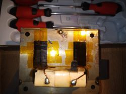
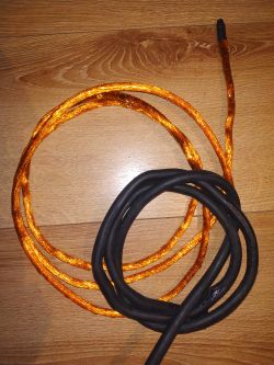
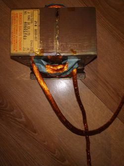
    Today I made modifications to the welding machine. The insulation was stripped from the 25 mm2 wire, instead I used two layers of Kapton tape and paper insulation (probably barley). Thanks to this, a few more turns came in and the voltage increased to 5 V.
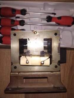
    View of the DIY welder interior with transformer parts and tools in the background. Close-up of a transformer with wrapped wires and yellow insulation tape. Coils of cables on a wooden floor. Transformer with wound copper wire, top view. Interior of a homemade spot welder using a transformer and copper wires.

    Update 10/11/2020.
    I have assembled everything, the result is 910 A. All that is left to do is to make electrode handles and the project is completed.
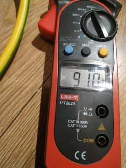
    Multimeter showing current reading of 910 A

    Cool? Ranking DIY
    About Author
    kulek855
    Level 13  
    Offline 
    kulek855 wrote 331 posts with rating 116, helped 10 times. Live in city Nisko. Been with us since 2008 year.
  • ADVERTISEMENT
  • #2 19031015
    Darek05
    Level 12  
    Hi
    Pretty decent execution,

    - how do the seals come out?
    - what are your welding times, number of pulses?

    I will add right away that your output voltage is too low, I recently finished my welding machine and did another one, for a friend and brother, for each of them after the first tests, where I wound the transformers with a 50 mm2 cable (I managed to insert 2 to 3 turns) , it turned out that the seals came out very poorly, the vast majority of them were not successful at all.
    Adjusting the welding time did not bring any good, increasing the welding time actually burned through the lamellae. 0.2 mm and links.
    The output voltage was then in the range of 2-3 V.
    The solution to this problem was to raise the voltage of the secondary winding to the level from 4 V to 5 V, currently I have 4 coils wound, the wire is 25 mm2 and the output is 4.3 V - each weld is perfect, pre-pulse time 10 ms, welding time 60 ms and regardless of the nickel or nickel plates used.

    For example, the upper welds 60 ms, lower 40 ms, welded plates 0.2 mm nickel plated.
    Cell welding machine on Chinese DIY driver
  • ADVERTISEMENT
  • #3 19031051
    radomski99a
    Level 10  
    From this you should get at least 900-1100 A. There are many mistakes here, but the best way is to look for yourself rather than ask for advice. I have been building my welder for over 1.5 years, perfecting every detail.
    By searching, you gain experience.
  • #4 19031233
    kulek855
    Level 13  
    Darek05 wrote:
    - how do the seals come out?
    - what are your welding times, number of pulses?

    The welds at 0.15 mm nickel plate come out nice for me, that's what I use.
    1 pulse, time 0.2, I set the welding power to the maximum value. Yes, realizes that the voltage is low. When I need more power, I will replace the cable with a longer or thicker one, of course without insulation, as mentioned below.


    I do not have photos, but if you are interested, I put a link to the video in which I weld the package to the screwdriver:


    radomski99a wrote:
    There are many mistakes here

    I'm only interested in security bugs, but I'm open to any feedback anyway. The power of the nickel plate welder is sufficient, if I want to weld nickel, I will replace the cable for 35 mm2, wrapped with Kapton tape + glass fiber tube. Please note that my mediocre, as mentioned above, has a scale of up to 600 A, so I cannot say to what extent the result above 700 A that he indicated corresponds to reality. best regards
  • #5 19032186
    dariuszw4
    Level 11  
    Nice layout, nicely made, I made a welding machine myself, but I went the simpler way, my control system consists of exactly 10 electronic components, smooth pulse time adjustment using a sliding resistor, the system is functional, works flawlessly and is without reservations.
  • #6 19032492
    kulek855
    Level 13  
    If it works and it works without failures, that's fine.

    Thanks for the opinion.

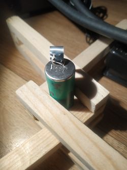
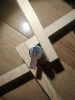
    So I quickly checked the new electrodes:
    Cylindrical battery with a protruding electrode placed on a wooden stand. New electrode mounted in a wooden frame.
  • #7 19032595
    KrRis
    Level 12  
    I have a question: how did you record a video on YouTube that you can see everything how you work? A webcam on the head or what? Best regards and congratulations on a successful project.
  • #8 19032815
    kulek855
    Level 13  
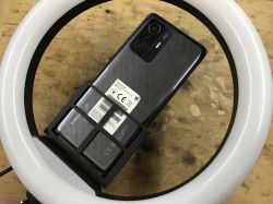
    Thanks. The key here are two photo bulbs placed on tripods. Sometimes I put on softboxes, they give a better effect.
    I shot the film with the Redmi 6 phone placed on a photo tripod. Regards too.
  • #9 19032842
    KrRis
    Level 12  
    Well, this video came out very well and professionally, it's nice to watch. I asked because I would like to start having fun with filming my work and uploading it to my website (or YouTube, in fact). You can write down what kind of tripod you used (I know it's off-topic, but if you can ask, I'll be grateful).
  • ADVERTISEMENT
  • #10 19032920
    kulek855
    Level 13  
    KrRis wrote:
    You can write down what kind of tripod you used (I know it's off-topic, but if you can ask, I'll be grateful).


    I used the Triopo GX-1127 Carbon with the Triopo B2 head and a phone mount for a few zlotys.
    You can safely use a cheap tripod - it does not matter when you are on the phone. I have the following lighting (two such sets):
    Link
  • #11 19033461
    radomski99a
    Level 10  
    See here the same driver with pure nickel 0.2 mm thick, the welding machine is able to weld any number of plates. Now I'm waiting for copper. I want to weld copper plates 0.2 mm.
    https://youtu.be/rtQBvazCI18
  • #12 19034129
    SylwekK
    Level 32  
    Darek05 wrote:
    I will add right away that your output voltage is too low

    I will add that you are not truthful ;-) If you don't believe me, I invite you to see my design. Link at the bottom in featured.
  • #13 19034189
    radomski99a
    Level 10  
    SylwekK, do you weld anything other than a nickel-plated plate? With pure nickel, the higher the tension, the better the welding.
  • #14 19034207
    SylwekK
    Level 32  
    I weld, e.g. stainless steel.
  • ADVERTISEMENT
  • #15 19034217
    radomski99a
    Level 10  
    I meant welding to cells. There, either nickel-plated steel or almost pure nickel is used (almost, because the nickel content is 99.6%), it is about the shortest possible welding time. I am welding nickel with a time setting of 20-40 ms. I know from experience that the higher the voltage, the better the welding.
  • #16 19034279
    Darek05
    Level 12  
    SylwekK wrote:
    Darek05 wrote:
    I will add right away that your output voltage is too low

    I will add that you are not truthful ;-) If you don't believe me, I invite you to see my design. Link at the bottom in featured.


    Maybe so, but in your construction the length of the cables leading to the electrodes has been reduced to the necessary minimum and the 2.9 V looks that it is enough. In my welding machine it did not work, even though I initially had a 50 mm2 wire, it was the same in the other two, which I made in parallel. I would like to add that the electrode cables initially brought out were also 50 mm2. Raising the voltage to 4-5V solved my problems and others. To illustrate the design differences, I enclose photos of my welding machine, currently the electrode wires are 25 mm2 due to its high flexibility, 50 mm2 was too stiff.

    Cell welding machine on Chinese DIY driver Cell welding machine on Chinese DIY driver Cell welding machine on Chinese DIY driver
  • #17 19034283
    SylwekK
    Level 32  
    @ radomski99a, see the bottom of the post. Nickel-plated sheet (i.e. the most popular). The lowest parameters that I can set, i.e. 10ms / 10ms, create a durable and nice weld.
    https://www.elektroda.pl/rtvforum/topic3558528-60.html#17903368

    @ Darek05, such a formal question - did you take out this unnecessary core with luck? I am asking because not all remove it and later complain of poor performance.

    Darek05 wrote:
    but in your construction the length of the cables leading to the electrodes has been reduced to the necessary minimum and the 2.9V looks that it is quite enough

    I have an additional module with wires like in a free welding machine, a total of about +80 cm - I do not see a difference in power.
  • #18 19034312
    Darek05
    Level 12  
    Quote:
    [...] @ Darek05, such a formal question - did you take out this unnecessary core with luck? I am asking because not all remove it and later complain of poor performance.


    Yes, I blew inductive bridges.
    It is possible that the welding sockets used are an effect of this.
  • #19 19037656
    Block3r
    Level 14  
    I was interested in this driver from Aliexpress. Is there a fundamental difference between the 40A and 100A versions?
  • #20 19037803
    kulek855
    Level 13  
    Block3r wrote:
    Is there a fundamental difference between the 40A and 100A versions?

    In a single-phase network, 40 A is more than enough.
  • #21 19037902
    Block3r
    Level 14  
    I guess so, because I have a 25 A protection. I meant that Chinese products often do not keep parameters - this 100 A will probably last longer.
  • #22 19046894
    mmaker
    Level 19  
    Hi, I also made such a welder for cells and after a minor modification, consisting in removing the inductive bridges from the transformer, I have an output voltage of 2.7 V (35 mm2 wire ;) . At 10ms / 10ms pulses, beautiful welds come out, practically like factory ones, it is impossible to tear the plate without damaging it. I use a 10mm / 0.2mm plate.
    Housing made of inverter welding machine, electrodes made of copper wire 4 mm.

    Cell welding machine on Chinese DIY driver
  • #23 19686108
    airman
    Level 13  
    If anyone has the possibility, please check at which point in the network waveform the triac is triggered in these Chinese drivers. Thank you and best regards :)

Topic summary

The discussion revolves around the evaluation and improvement of a DIY cell welding machine constructed from repurposed materials. The user seeks feedback on their design, which features a 1300 W transformer with a secondary winding voltage of 3.3 V and a short-circuit current of 750 A. Suggestions include upgrading the cable from 25 mm² to 35 mm², using hydraulic presses for ring terminals, and replacing aluminum components with copper for better conductivity. Participants share their experiences with welding parameters, noting that increasing the secondary voltage to 4-5 V significantly enhances weld quality. Various configurations and modifications are discussed, including the removal of inductive bridges and the use of different electrode materials. The conversation also touches on the performance of different drivers sourced from Aliexpress, with a focus on the 40 A and 100 A versions.
Summary generated by the language model.
ADVERTISEMENT