logo elektroda
logo elektroda
X
logo elektroda

Analogue cell sealing machine

Wszechelektronik 4218 27
ADVERTISEMENT
Treść została przetłumaczona polish » english Zobacz oryginalną wersję tematu
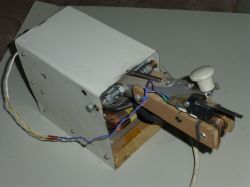
  • Homemade welder with metal components and a wooden base. .
    I built a welding machine a few years ago, it was mainly to be used to weld cells into packages. I have a lot of cast-off components, so I'm trying to put at least some of them to some use. Unfortunately this is going with increasing resistance, but that's another topic. So the result is a rather unusual, processorless circuit, altogether simple and cheap, but not lacking in important features. Many welding machine controllers have a disadvantage, despite a stable pulse time, there is no control of the moment when the transformer is connected to the mains, and in the mains, as it is in the mains, the voltage changes all the time. As a result, the portion of energy supplied to the welding spot varies, which can result in burning out the cell or in too weak a weld, as well as overloading the network and tripping the protections. With this in mind, this design was developed:
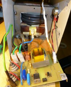
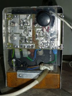
    Homemade spot welder with visible electronic components and wires .
    Unfortunately, as it turned out after commissioning, there was a welding time instability, burning out one in 20-30 cells. A ghastly occurrence, fortunately nothing exploded, but you had to pry this burnt cell out of the pack, so overall a big bummer. I tried to find the cause of this instability, modified something there, but it didn't get much better until I finally put the circuit away for lack of time. I occasionally used this welder, with small packets the job usually worked.
    Quite recently the need arose to weld a larger packet, I decided to redo the whole controller at the same time.
    A schematic was created:
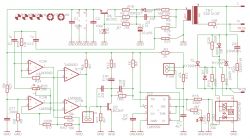
    Electrical schematic of a microcontroller-free spot welder. .
    Maybe it will be useful for someone, also a simple chip without a processor, whether this is a disadvantage or an advantage I will leave to the readers to choose.
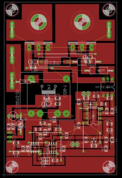
    Untreated board, specially designed for my CNC woodworker. Simple copper layer cuts, significant milling inaccuracy allowed, easy post processing.
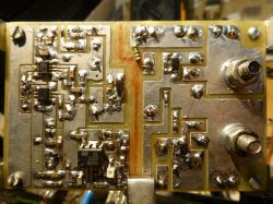
    Electronic circuit on a PCB with visible connections and soldered components. .
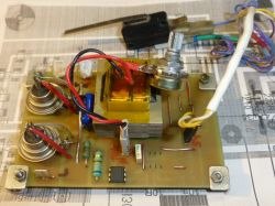
    The new arrangement worked well, I welded the package, almost 300 good welds
    in a row, except that... wanting to speed up the work, the driver was still in spider form, I made the board later. After fitting the new board, I did a few test welds, and it seems to work just as well, which is not at all obvious. Those who know know that spiders can work sensationally, and it is only the making of the plate that spoils the effect. ;)

    How it works.
    The power circuit consists of a 10-20V 2W transformer, a single-pole rectifier, a single-transistor voltage limiter-stabiliser feeding the circuit. The AC voltage from the transformer via the divider goes to the phase shifter IC3A and further to the comparators that detect the zero crossing, Zero in this circuit is half the supply voltage. The phase shifter is there to be able to hit the peak of the sine wave, which is when there is the least current surge when switching on the high-power tray. Is this successful? Experiments show that this surge can indeed be reduced by adjusting the phase with potentiometer R25. A shifted zero is detected which indicates the peak of the sine wave. A pulse at the peak of the mains voltage appears at the output of the comparators. This signal via the S microstep triggers the LM555 timing circuit. Then it is typical, the optotriac switches on the thyristors, I wanted to use what I have, so here sit the Russian KY202h, but if I burn them all, you can of course insert other newer ones, the board is quite universal.
    Power trafo standard from microwave, 4 coils I think 16mm, long time ago I wound it I don't remember exactly.
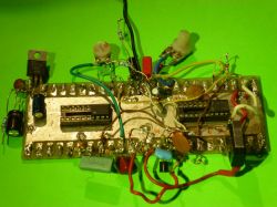
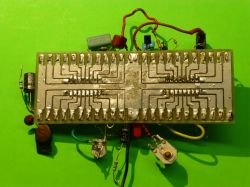
    Electronic circuit board with soldered components on a green background. Prototype electronic circuit with an unetched board on a green background .
    Spider testing platform. :) .

    DIY spot welder with a makeshift construction, consisting of a metal and wooden casing. Close-up of a homemade spot welder with a circuit board and electrical components mounted in a metal casing on a wooden base. PCB schematic for a spot welder controller Circuit board with control system featuring transformers and electronic components. Circuit board with control system featuring transformers and electronic components. .

    Cool? Ranking DIY
    About Author
    Wszechelektronik
    Level 13  
    Offline 
    Wszechelektronik wrote 94 posts with rating 155, helped 1 times. Been with us since 2011 year.
  • ADVERTISEMENT
  • #2 21299305
    Anonymous
    Level 1  
  • ADVERTISEMENT
  • #3 21299332
    jarekgol
    Level 39  
    Metering in such a system would be done on some RC anyway.
    As for the welders, the industrial ones support regulation of time (number of grid periods) and phase angle. Plus some ramping, repetition and other niceties, as in ASPA controllers.
    I used to work in fence panel welding and sometimes had to change these parameters.
    I'm also curious about the issue of the tray switching in a voltage spike, I've heard this theory, I wanted to test it on my desk one day and it was quite random.
  • #4 21299442
    Anonymous
    Level 1  
  • #5 21299532
    gulson
    System Administrator
    Brave design, yes without a processor hmm. Out of curiosity why the choice without a processor, advantages/disadvantages?
    Do you perhaps know what caused the instability of the previous solution? Any further improvements?

    I'm impressed with the analogue solution, good old school.
    Send a Parcel Post and I'll send a small gift.
  • #6 21299557
    jarekgol
    Level 39  
    @jewishmakaron does this apply to a transient such as switching on? After all, if you switch on at zero, no current will flow (and according to the principle it should automatically generate current).
    I once took a trafo and an oscilloscope to measure the current and voltage on it, switched it on with a pin at random times and did not observe any regularities. Yes, it does happen that a transformer takes more current at start-up than it takes afterwards, we all know this and hear it from time to time, except that I have not been able to find a correlation on my own desk.
    There is also a version about core remagnetisation, but the problem is similar to the one above.
  • #7 21299648
    acctr
    Level 38  
    ledo99 wrote:
    Wszechelektronik wrote:
    The phase shifter is here to be able to hit the peak of the sine wave, that's when there is the least current surge when switching on a high-power tray.


    Isn't it simpler to time 1/4 of a period from passing through "0" which should work out very close to max ?
    .
    Does the phase shifter do something else?

    jewishmakaron wrote:
    jarekgol wrote:
    I'm also curious about the issue of the tray switching in the voltage peak, I've heard this theory, I wanted to test it on my desk one day and it was pretty random.


    According to the phase shift of current and voltage (ULICU CIUL or LUIC principle), the voltage precedes the current in the coil by 90 degrees.

    Wrong, the offset between current and voltage is not relevant here, but if anything it is the offset between voltage and magnetic flux.

    In the case of the tray and this pulse created when it is switched on, the current and voltage are in phase and the direct cause is the magnetisation of the core. At the zero crossing point, di/dt is highest which translates into maximum flux. The already magnetised core magnetises additionally, so that it becomes saturated and the current increases, limited only by the winding resistance.
    Helpful post? Buy me a coffee.
  • ADVERTISEMENT
  • #8 21299709
    jarekgol
    Level 39  
    @acctr so in theory it should matter at what point the trafo was switched off previously ? Was it in quotes "magnetised to N or S" ?
  • #9 21299739
    acctr
    Level 38  
    jarekgol wrote:
    so theoretically it should matter at what point the trafo was switched off previously? Was it in quotes "magnetised to N or S" ?
    .
    Yes, it matters in practice too and that's where the impulse comes from.
    But switching on at the peak of the sine ensures that the core does not become saturated.
    Roughly speaking, it looks like this: as a result of the magnetisation in the core, there is initially a flux Φr, we switch on the grid and hit zero. Then in the worst case the flux increases by an additional value Φz. If we switch on at max sine, the flux increases by Φm. The relationship Φz = 2 Φm is important here.
    This is taken from the fact that Φz increases for 10 ms and Φm for 5 ms.
    This is all due to the initial conditions and once the trafo has worked for a few s, the flux stabilises.
    Helpful post? Buy me a coffee.
  • #10 21300074
    keseszel
    Level 26  
    acctr wrote:
    jarekgol wrote:
    so in theory it should matter at what point the trafo was switched off previously? Was it in quotes "magnetised to N or S" ?
    .
    Yes, it matters in practice too and that's where the pulse comes from.
    But switching on at the peak of the sine ensures that the core does not become saturated.
    Roughly speaking, it looks like this: as a result of the magnetisation in the core, there is initially a flux Φr, we switch on the grid and hit zero. Then in the worst case the flux increases by an additional value Φz. If we switch on at max sine, the flux increases by Φm. The relationship Φz = 2 Φm is important here.
    This is taken from the fact that Φz increases for 10 ms and Φm for 5 ms.
    This is all due to the initial conditions and once the trafo has worked for a few s, the flux stabilises.

    So a better solution would be to switch on the secondary rather than the primary.... , but currents..fact....
  • #11 21300140
    drunek
    Level 25  
    Super project! I'm delighted that there are still some hobbyists who can create something practical from scratch, and without a microcontroller. I'll have a look at the schematic when I have a moment.
    It would be great if you published an article about it in "Understanding Electronics" by Piotr Górecki.

    gulson wrote:
    Bold design, yes without a processor hmm. Out of curiosity why the choice without a processor, advantages/disadvantages?
    .
    But what is it for here? I don't see the use.
  • #12 21300249
    metalMANiu
    Level 21  
    acctr wrote:
    It roughly looks like this: as a result of the magnetisation in the core, there is initially a flux Φr, we switch on the grid and hit zero. Then in the worst case the flux increases by an additional value Φz. If we switch on at max sine, the flux increases by Φm. The relationship Φz = 2 Φm is important here.
    This is taken from the fact that Φz increases for 10 ms and Φm increases for 5 ms.
    .
    I appreciate with what ease you have managed to explain this :) .
    If the time during which the flux increases is so important, why not turn on the transformer e.g. 2 milliseconds before going through 0?
  • #13 21300283
    acctr
    Level 38  
    metalMANiu wrote:
    why not turn on the transformer e.g. 2 milliseconds before going through 0?
    .
    Because this is closer to zero and the risk of core saturation increases. The peak of the sine, at least the 'real' one, is the same distance from the 'left' zero transition and the 'right' one, so we have the same chances that the flux will not cause core saturation for both N and S. And what the residual flux in the core will be, and whether there will be any at all, is a lottery.
    Helpful post? Buy me a coffee.
  • #14 21300568
    Anonymous
    Level 1  
  • ADVERTISEMENT
  • #15 21300590
    Wszechelektronik
    Level 13  
    gulson wrote:
    Bold design, yes without processor hmm. Out of curiosity why the choice without a processor, advantages/disadvantages?
    .
    If it's possible to achieve the intended functionality by combining a dozen or so simple components, then I guess it's worth taking advantage. Maybe it's out of habit, my adventure with programming ended in the late 90s with the scrapping of atari computers. I didn't resent the processors, none of that. It's just that the limited time and simultaneously increasing amount of interesting/necessary activities exceeded human capacity at some point. I had to choose whether to sit around with a soldering iron in old junk or to chase the novelties. Unfortunately, my computer knowledge suffered greatly, and I would not be able to write a good program now.
    gulson wrote:
    Do you perhaps know what caused the instability of the previous solution?
    .
    Probably interference from the power tray, because after adding a piece of steel plate between the trafo and the board it helped a bit. The control part was completely different, the concept was created in a rather old simulator, and there you know interference is absent, just pure maths. :) .
    gulson wrote:
    Any further improvements?
    Any further improvements?
    Maybe there will be a thicker wire in the traffic, as pure nickel plate welds do not succeed, only nickel plated ones do. I do not foresee any further changes for the time being, as the device will not be used often anyway.
    drunek wrote:
    .
    It would be great if you would publish an article about this on "Understanding Electronics" by Piotr Górecki.

    Thanks to
    Writing articles is rather beyond my capabilities, more knowledge of theory is needed, and I would sooner solder something than calculate.:)
  • #16 21300610
    drunek
    Level 25  
    Bottom line.
    What kind of thyristors should these be, i.e. for what anode current? I can see that a triac is unlikely to replace this.
  • #17 21300670
    mfac
    Level 17  
    >>21299739 This is about something else. I can't remember with details, but the issue breaks down into differential equations, the principle of continuity of current, the dphi/dt relationship etc. At start-up there is an exponential component of the current, and its peak value depends on the voltage derivative at the moment of switching on. Someone wrote that >>when there is 0V then the current won't flow<< - well, yes, at the moment it won't, but a few ms later physics will pick up where it leaves off - to preserve...something there. And residual flux issues also add their 5 gr.
  • #18 21300671
    keseszel
    Level 26  
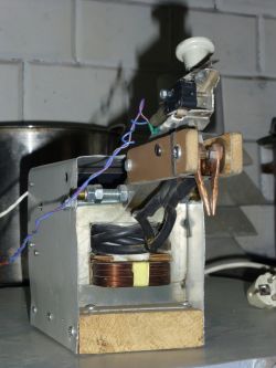
    I was intrigued by the handle. A very ingenious solution, a total gimela ;-) . You have used copper wire, of some thickness.... I see that it's vaulted at one end, with the other ground down. How long does it last, did you have to grind it often? How about scorching, sticking, carbon build up. Have you tried other tips? I was trying on carbides from a battery for example, as someone wrote that they work quite well.

    Standard layout on 555. on the net someone was selling such drivers, they worked moderately. A couple of people modified it and it worked fine, no shifters.
    I was thinking of buying a microprocessor one, but there was a lot of information about failures due to a Chinese error, I can't remember which one anymore.

    I was most impressed with the handle though!!! I relied on it because I have ended up with bull ends, I don't even remember what they are anymore.
  • #19 21300881
    Wszechelektronik
    Level 13  
    drunek wrote:
    Alright.
    What kind of thyristors should these be, ie for what anode current? I can see that a triac is unlikely to replace this.
    .
    The ones I've inserted have a max of 10A/400V, although in pulse they can probably handle a lot more, so far I haven't burned any. Maybe with a thicker winding there would be a problem. This arrangement of two thyristors is better not changed to a triac. Of course I didn't invent it, it's supposedly the most fail-safe tested solution. I just added a transil at 350V, in addition to the RC surge suppressor.

    Added after 6 [minutes]: .

    keseszel wrote:
    I was interested in the handle. A very ingenious solution, a total gimela ;-) . You have used copper wire, of some thickness.... I see that it's vaulted at one end, with the other ground down. How long does it last, did you have to grind it often? How about scorching, sticking, carbon build up. Have you tried other tips? Brass ones for example. I was trying on carbide ones from the battery, because someone wrote that they work quite well.
    .
    I only sanded once, then every few dozen welds a small correction with a small file and frequent wiping with p600 paper. It is important to have a similar contact surface on both ends, because otherwise it sticks. In my case it was like that at the beginning, and when I evened out the surface it stopped sticking. The copper ones go quite well, I haven't tried the others.
    The only thing is that the wood in the handle is not very stiff, it likes to bend sideways, a thick laminate would be better. Both sides spring on the rubber band independently, if anyone wants to know. That's also important, because that way there's similar pressure on both ends.
  • #20 21303934
    misiek84LG
    Level 12  
    Super project, I will try to copy in the near future.
    How much 16mm cord so roughly needed to make 5 or 6 coils on a microwave core?????
  • #21 21304463
    Wszechelektronik
    Level 13  
    >>21303934 250cm should be enough.
  • #22 21304848
    ElectroTom
    Level 25  
    That spider testing platform is interesting. I think I will make one, thanks.
  • #23 21307649
    sq2aki
    Level 11  
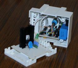
    I see , the topic is new so I dug out my old welder, removed the controller and played around with it a bit. The welder wasn't used to weld cells, just the little tin shielding cups. But maybe I'll convert it to a cell welder as it lies useless? It's an old project, in the age of microprocessors it may look ridiculous, but it works.


    Opened casing of a welder showing the electronic controller inside. .

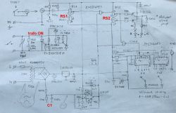
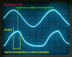
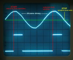
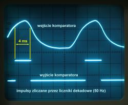
    The controller turns the thyristors on in a sine wave pattern and off in zero. There is no timing circuit, it just counts the 50 Hz mains pulses. There is a comparator on the 50 Hz input, which gets the signal shifted in phase by C1 so that the turn-on hits the peak of the sine wave. There are 2 RS flip-flops on the trigger input. The first is triggered by the START button and the circuit waits until the peak of the sine wave from the mains arrives. When the peak arrives, the second RS switch controlling the optotracer is switched on and 50 Hz pulses are applied via the gate to the 4017 counters. After the set number of periods has been counted down, both RS flip-flops are reset and the circuit waits for the START button to be pressed again. The number of periods is set by a mechanical switch with a step of 20 ms.

    I have shown the operation on oscillograms with description, maybe it will be useful for someone. Unfortunately I only have this old working schematic, but the circuit is also a vintage now.

    Sketch of an electronic circuit diagram for a welder controller with labeled components on paper. Oscillogram displaying two sine waves with labels: szczyt sieci 230V, napięcie na wejściu komparatora, START, wyjście komparatora w stanie wysokim. Oscillogram showing a sinusoidal waveform with start and stop markers. Oscillogram showing the operation of a welder with labeled signals at the comparator input and output. .
  • #24 21307666
    jarekgol
    Level 39  
    @sq2aki From the first oscillogram it looks like the negative halves are skipped? Is it supposed to be like that or am I seeing things wrong?
  • #25 21308276
    sq2aki
    Level 11  
    Yes, the negative halves are ignored when counting pulses. Of course, a transformer made of MOT gets a full sine wave from the grid.

    The input comparator only reacts to positive halves and thus the circuit counts full periods for 50 Hz. If the negative halves were not omitted, the resolution of the adjustable time could be increased to 10 ms, but the maximum time would then be 1 s.

    In this circuit, you can only set times from 20 ms to 200 ms in 20 ms steps, then 200 ms to 2 s, in 200 ms steps. That is, you cannot set a time of, for example, 260 ms.

    This circuit could be improved by using an AND gate in front of the switches instead of diodes. Then it would be possible to set an arbitrary time in 20 ms increments just like you set the resistance in a decade resistor. But for simple welding of tin boxes such a circuit was sufficient, you could select with a simple switch only 12 preset times (the switch has 12 positions). For cell welding, however, this circuit needs to be modified.
  • #26 21308312
    jarekgol
    Level 39  
    sq2aki wrote:
    Of course a transformer made with MOT gets a full sine wave from the mains.

    Well that's mainly what I meant, as I see the triggering is for the top half and to my mind only a portion of it should go to the trafo. As it's triggered at the peak it's no longer going to be a full sine wave, then as I'm positive half, I'm wondering if the whole lower half is being passed through? Because it seems to me from these oscillograms that it won't.
  • #27 21308724
    sq2aki
    Level 11  
    These oscillograms are from the controller, the example is for one period i.e. 20 ms. The upper half of the sine wave triggers only the RS2 metering device, not the thyristor. After triggering, the metering device maintains its state and supplies the optotracer diode for a fixed number of complete periods. These periods can be a pre-programmed number, min. 1, max. 100, giving a transformer operating time of 20 ms to 2 s.

    From the moment the second RS2 flip-flop is latched by the positive half of the sine wave, the optotriac continuously triggers the thyristors and applies AC current to the transformer, while the counter counts the pulses. When a high state appears at the counter's output, the one that is currently connected to the reset transistor by a switch, the flip-flop is reset and only then does the optotriac switch off and the thyristors cease to be triggered. However, the current will still flow for a very short time, until the sine wave passes through zero and the last triggered thyristor goes out.

    If only one half of the sine wave were applied to the transformer, core saturation and fuse blowing would already have occurred during the second period. (This can happen if one of the thyristors is damaged)

    Added after 36 [minutes]:

    And another note: there are two types of optotriacs - those that are triggered at a given time (random) and those that only turn on at zero. In this circuit, there must be an optotriac of the random type.

    The use of a zero-triggered optotriac will negate the advantages of the whole circuit. If a zero-triggered optotriac were used, despite being powered at the peak of the sine wave, the thyristors will only be triggered when they pass through zero.

    What are the consequences of energising a transformer at zero: Cheap MOT transformers have a relatively small core and are designed so that the core can only store the energy of one half-period. (The same is true of toroidal transformers.) When switched off, there is always residual magnetism left in the core. If there is a switch-on at zero, the core must absorb the energy of the entire half-period. If the magnetic flux generated by the current just happens to coincide with the residual magnetism, the core becomes saturated such a transformer will start to put up a very low resistance (equal to the resistance of the primary winding wire) and a very high current will flow. This will blow the fuse and may damage the thyristors. A phenomenon known from switching toroidal transformers with an ordinary switch, without a 'soft start'. When we energise the transformer at the peak of the sine wave, a moment after the start the core will have accumulated only half the half-period energy and, despite the addition of residual magnetism, it will not saturate, so the transformer will immediately start working normally.

    So why are zero-triggered optotriacs manufactured? To power capacitive loads, which must be switched on exactly at zero to avoid the current surge associated with rapid capacitance charging.
  • #28 21309089
    jarekgol
    Level 39  
    sq2aki wrote:
    The upper half of the sine wave triggers only the RS2 flip-flop, not the thyristor. Once triggered, the flip-flop maintains its state and powers the optotrace diode for a fixed number of complete periods.

    Conceived, mental eclipse I had, it was in the description from the start.
    Two opto versions I can recall, I tend to find the ones in zero, although I used to make myself a dimmer on a 2051 and specifically bought the ones with any switching moment.
    My father also told me that they (the ones with the zero crossing circuit) switch on when the voltage on them builds up to a hundred volts and this does cause problems as there are long wires and no choke. I'll have to look at it on an oscilloscope sometime. They are often used for heaters, they generate less trash in the network and controlling them is simpler - no need for synchronisation.

Topic summary

The discussion revolves around the design and functionality of an analog welding machine for battery cells, emphasizing the challenges of controlling energy delivery during the welding process. The original poster describes a processorless circuit that aims to stabilize the energy supplied to the welding spot, addressing issues like varying mains voltage and the risk of overheating cells. Participants discuss various technical aspects, including phase shifting, transformer magnetization, and the importance of timing in relation to the sine wave of the mains supply. Suggestions for improvements and alternative designs are shared, along with insights into the use of thyristors and the potential for further modifications to enhance performance.
Summary generated by the language model.
ADVERTISEMENT