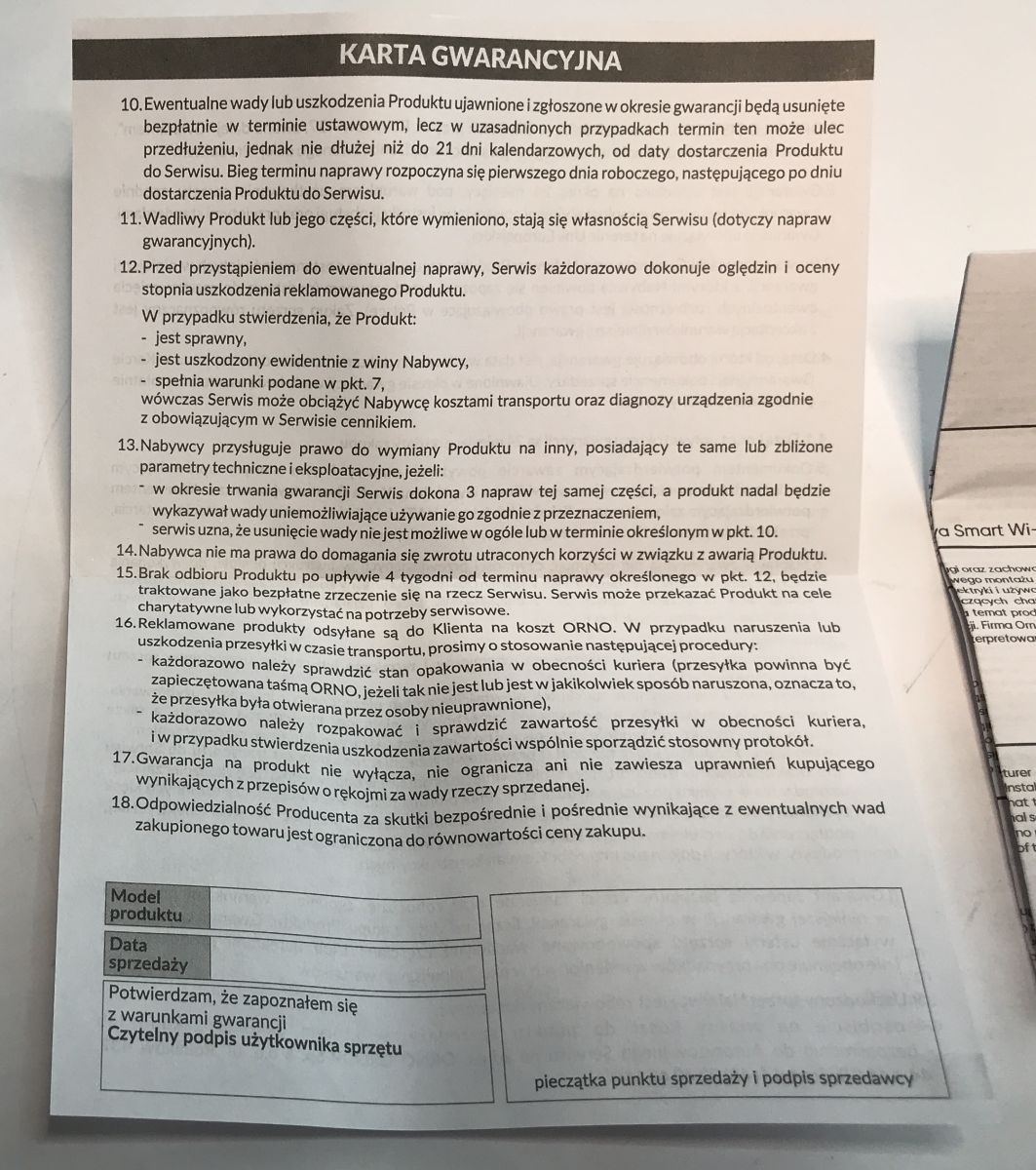
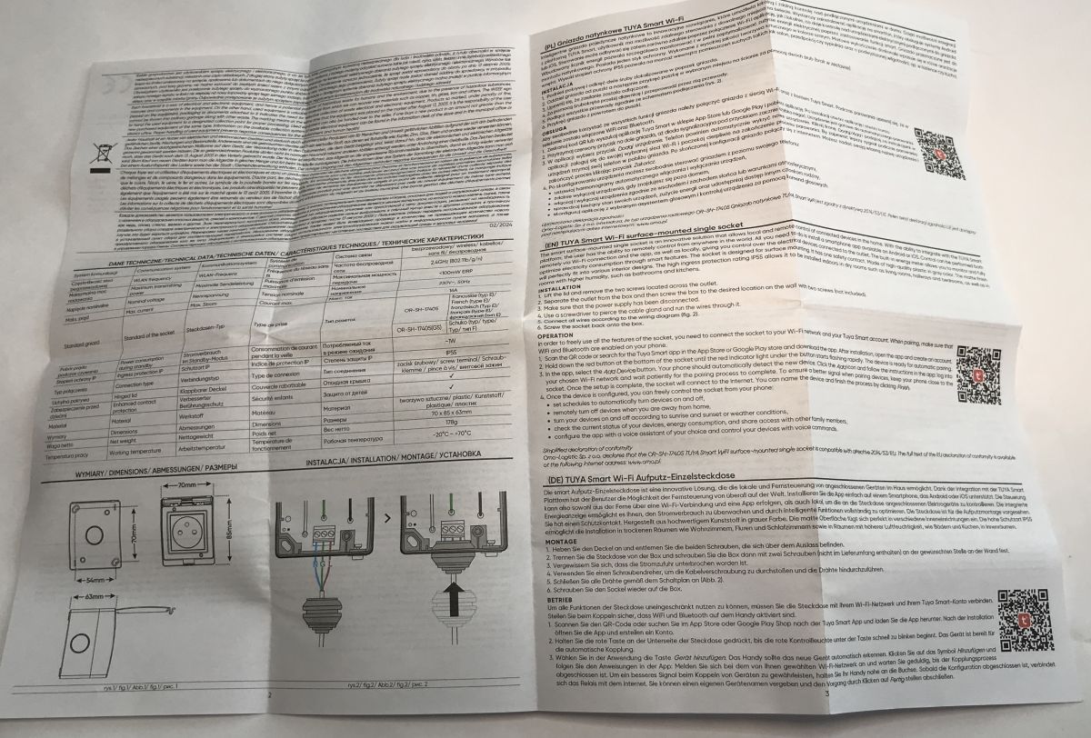
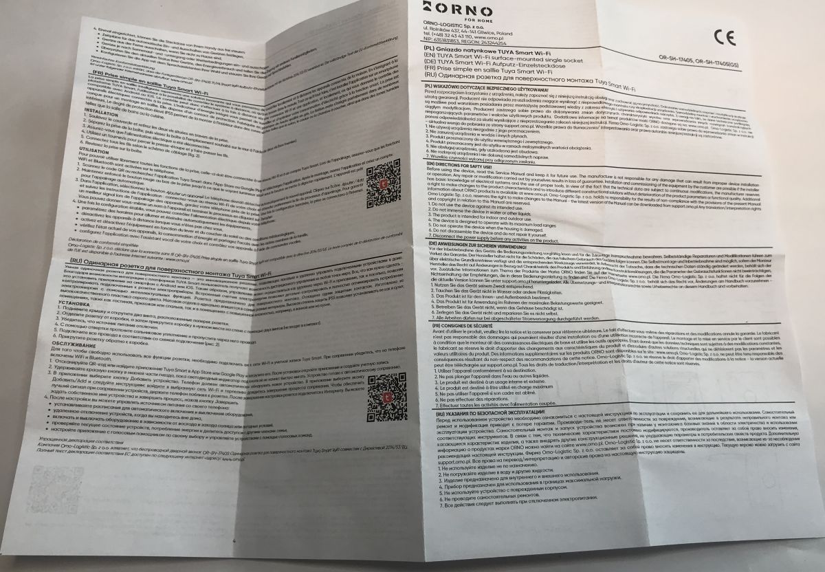
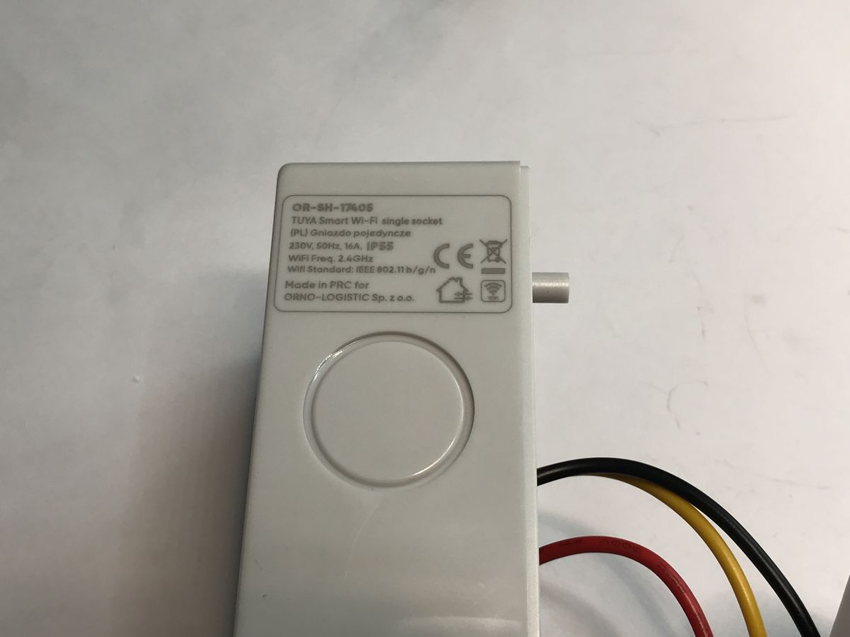
External WiFi controlled socket for Home Assistant - OR-SH-17405 IP55
TL;DR
- OR-SH-17405 IP55 outdoor WiFi-controlled socket with voltage, current, and power measurement is opened and converted from Tuya to local Home Assistant control.
- Inside, it uses a CB3S module based on BK7231N, a non-isolated KP15052SP supply, a 3.3V LDO, and BL0937 energy metering.
- The socket costs around PLN80, and the flasher maps relay P8, WiFi LED P9, button P7, plus BL0937 signals on P6, P24, and P26.
- Calibration still requires a 60W bulb and manual VoltageSet, CurrentSet, and PowerSet adjustments before the device is ready for accurate readings.
Generated by the language model.
 .
.
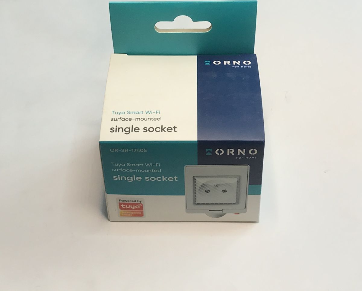
Here is a short presentation of the interior and the procedure for changing the firmware of an external WiFi-controlled socket, model OR-SH-17405. The product shown here additionally offers voltage, current and power measurement and normally works with Tuya, but after uploading the new software it will be possible to run it 100% locally and connect it to Home Assistant. The whole thing can be bought for around PLN80, although you could probably get it cheaper imported from overseas.
We get a box like this. The markings alone (WiFi + BT and Tuya) suggest the presence of the BK7231.
 .
.
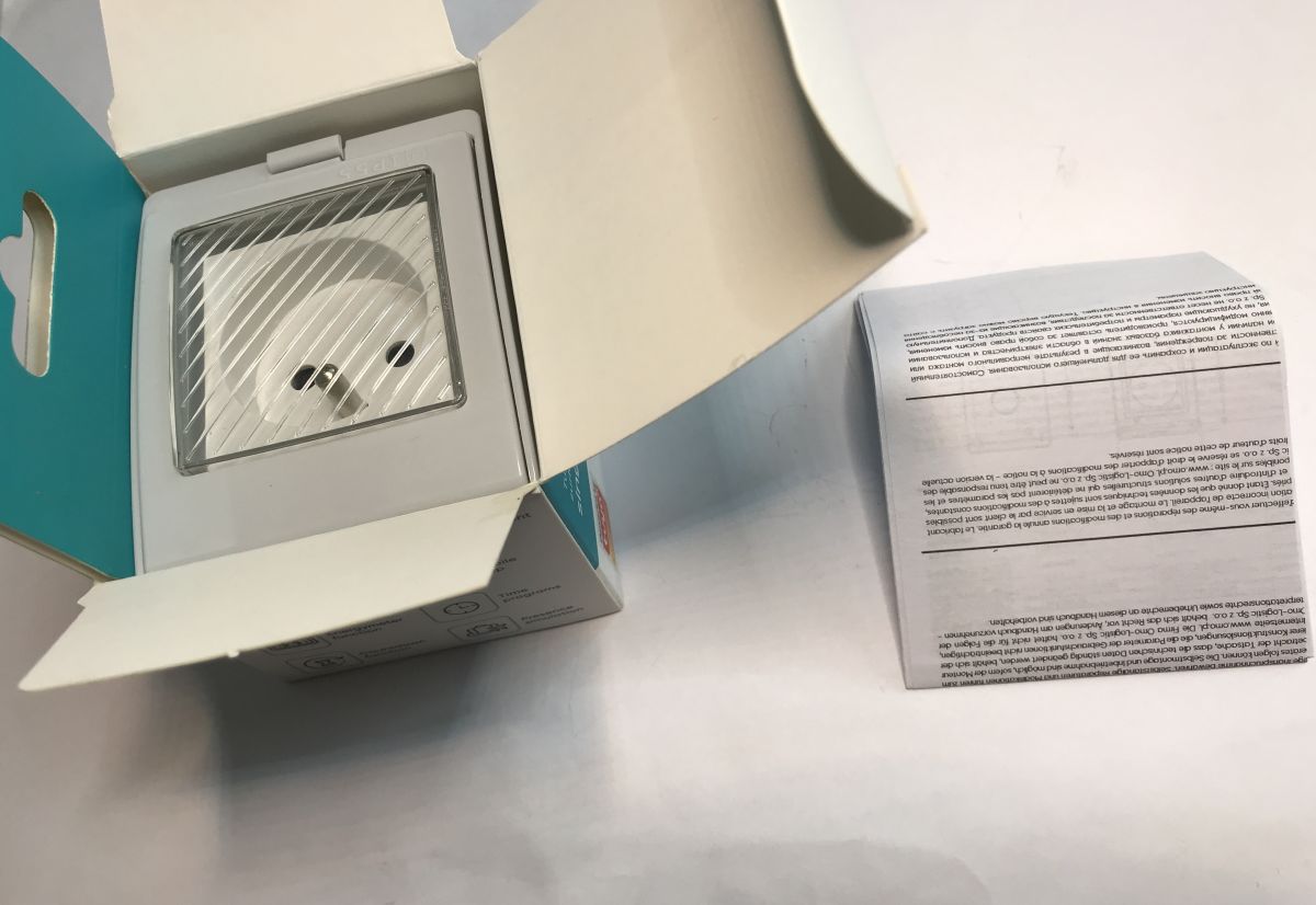
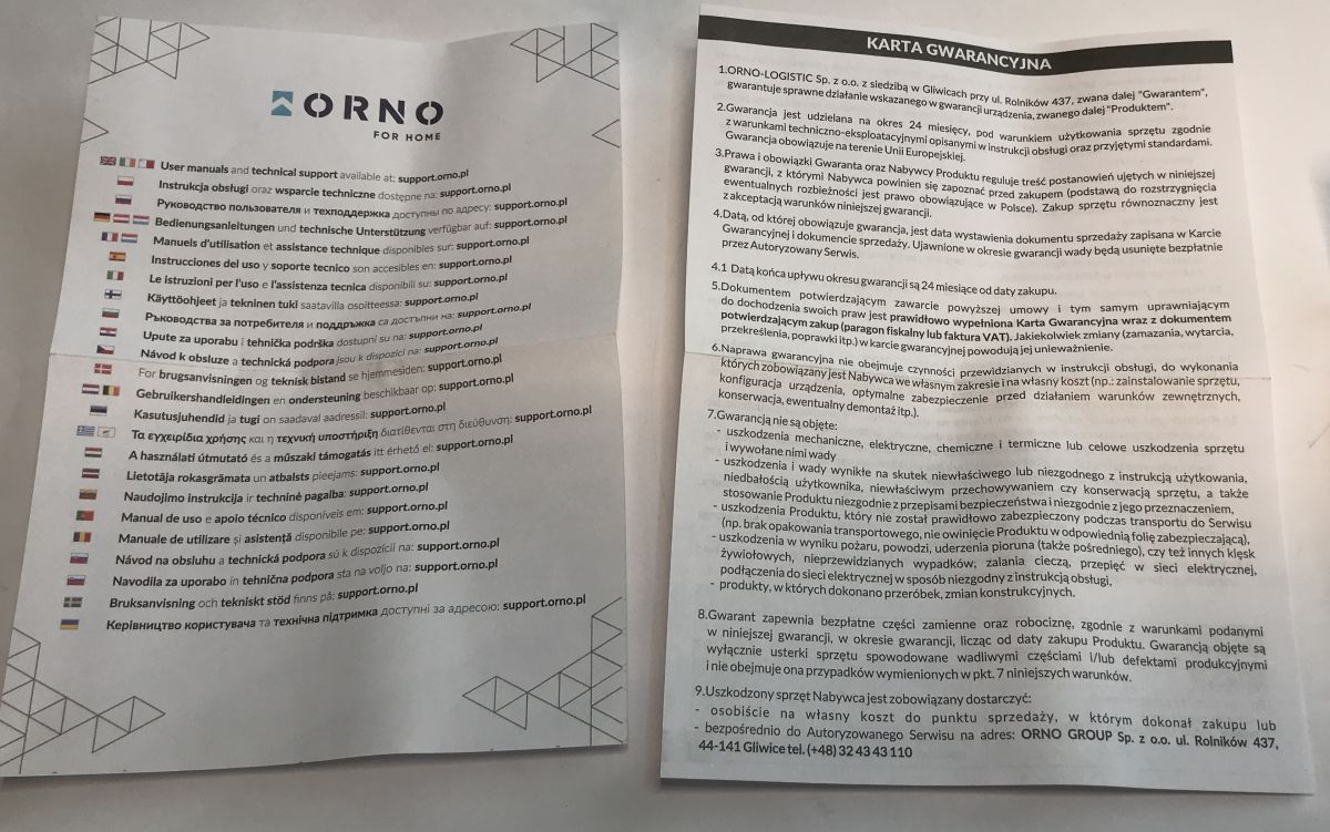
Multilingual manual:
 Multilingual manual.
 .
.
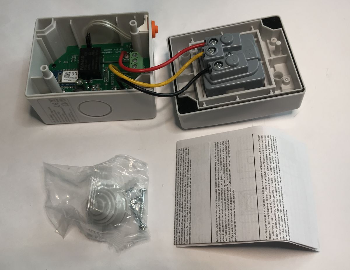
Screws and insulating collar included:
 .
.
There is a seal between the two parts of the housing to protect against humidity.
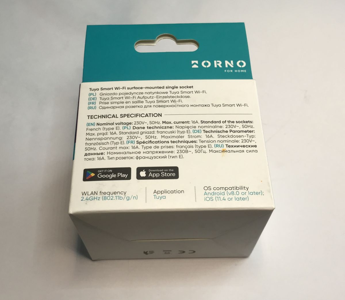
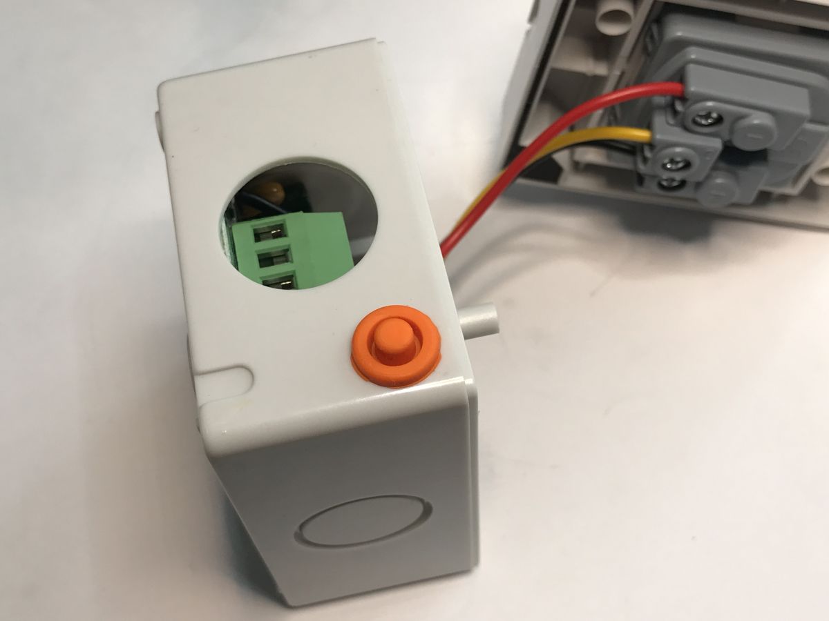
Markings, as in the title - OR-SH-17405:
 .
.
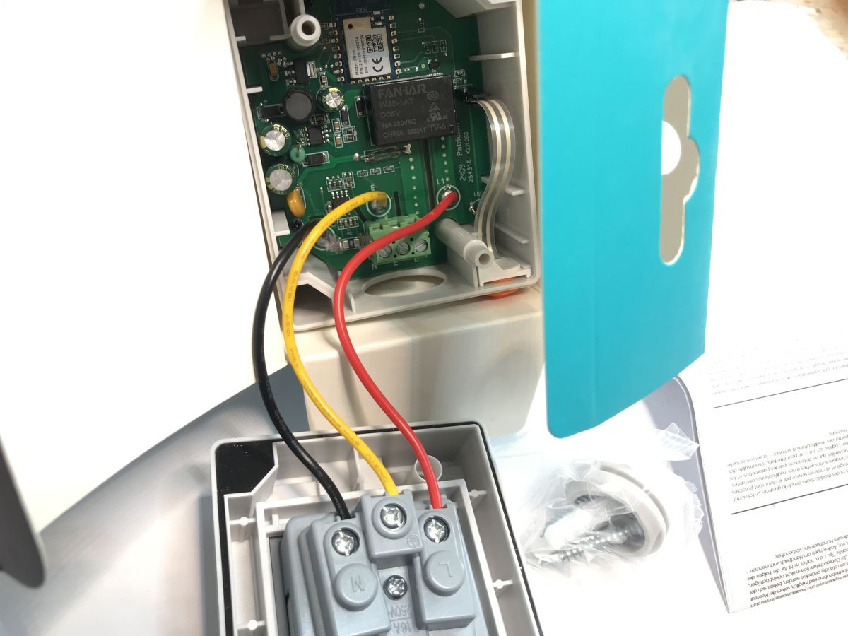
On the casing of the product there is a button with which the relay can also be switched in an emergency, even without access to WiFi.
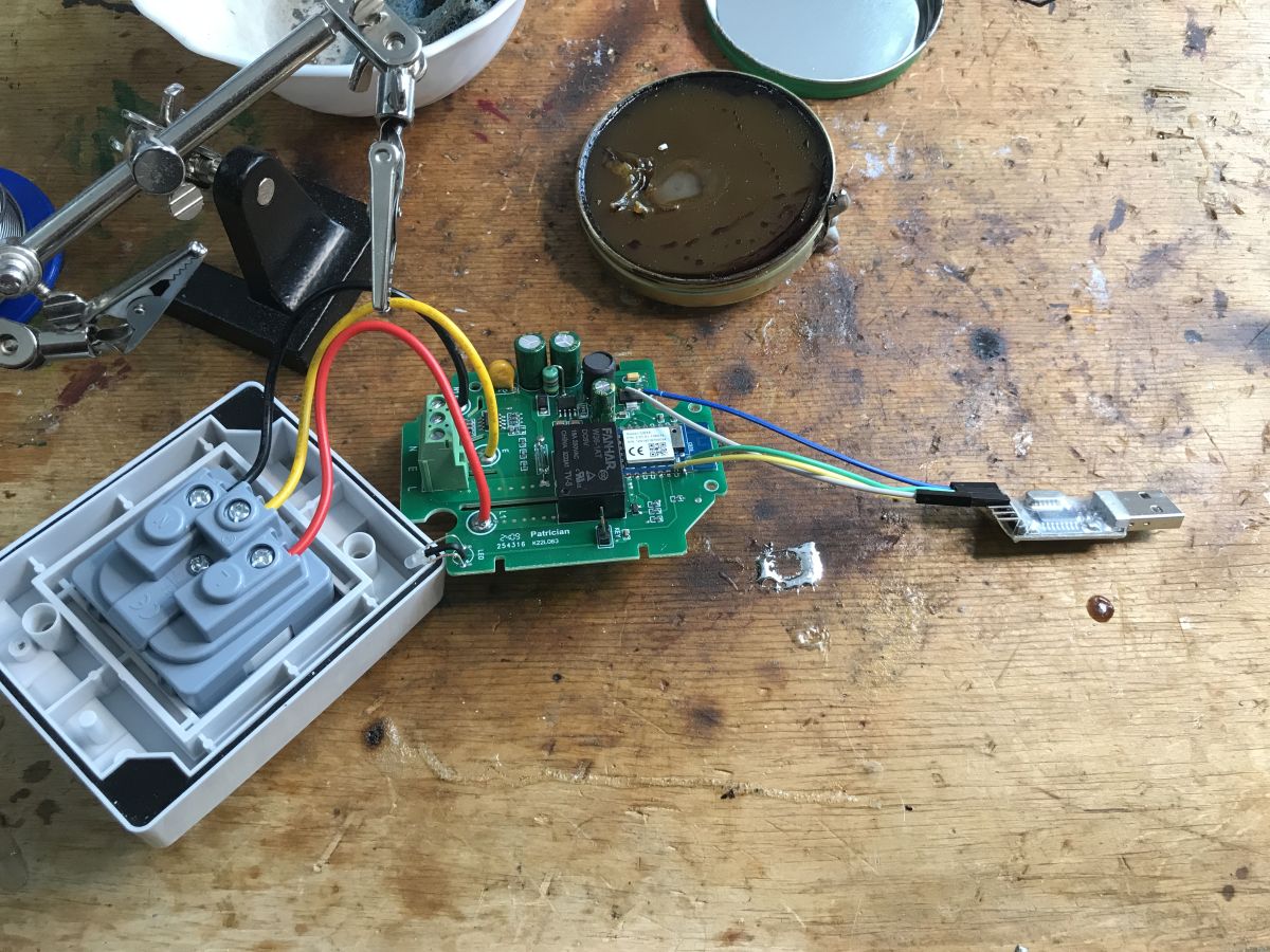
Let's take a look inside.
 .
.
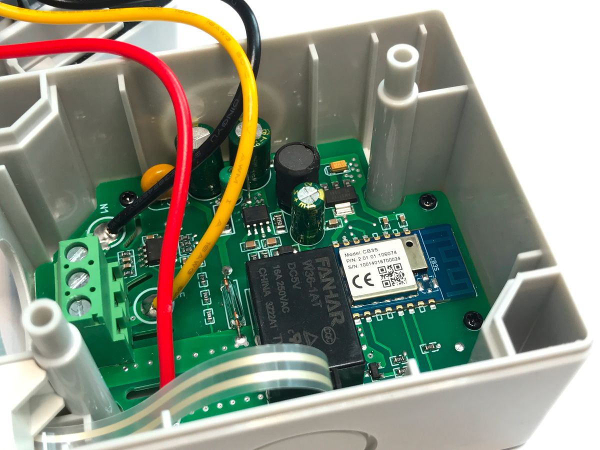
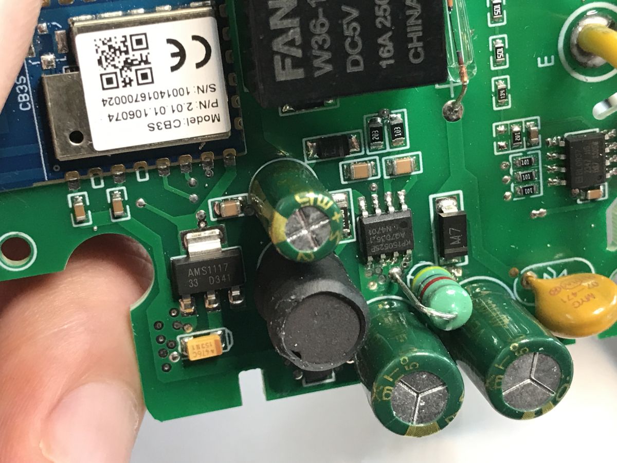
You can already see at this stage that the whole thing is based on the WiFi+BT CB3S module (BK7231N). I will soon show how to upload new software to it.
 .
.
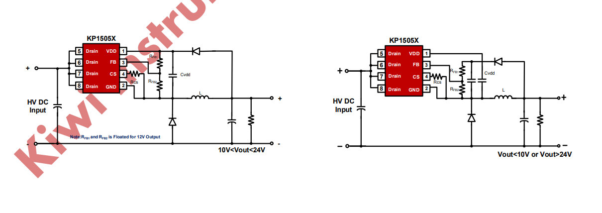
The power section has a non-isolated KP15052SP inverter and a 3.3V LDO powering the WiFi module:
 .
.
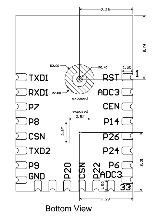
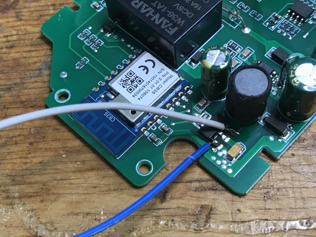
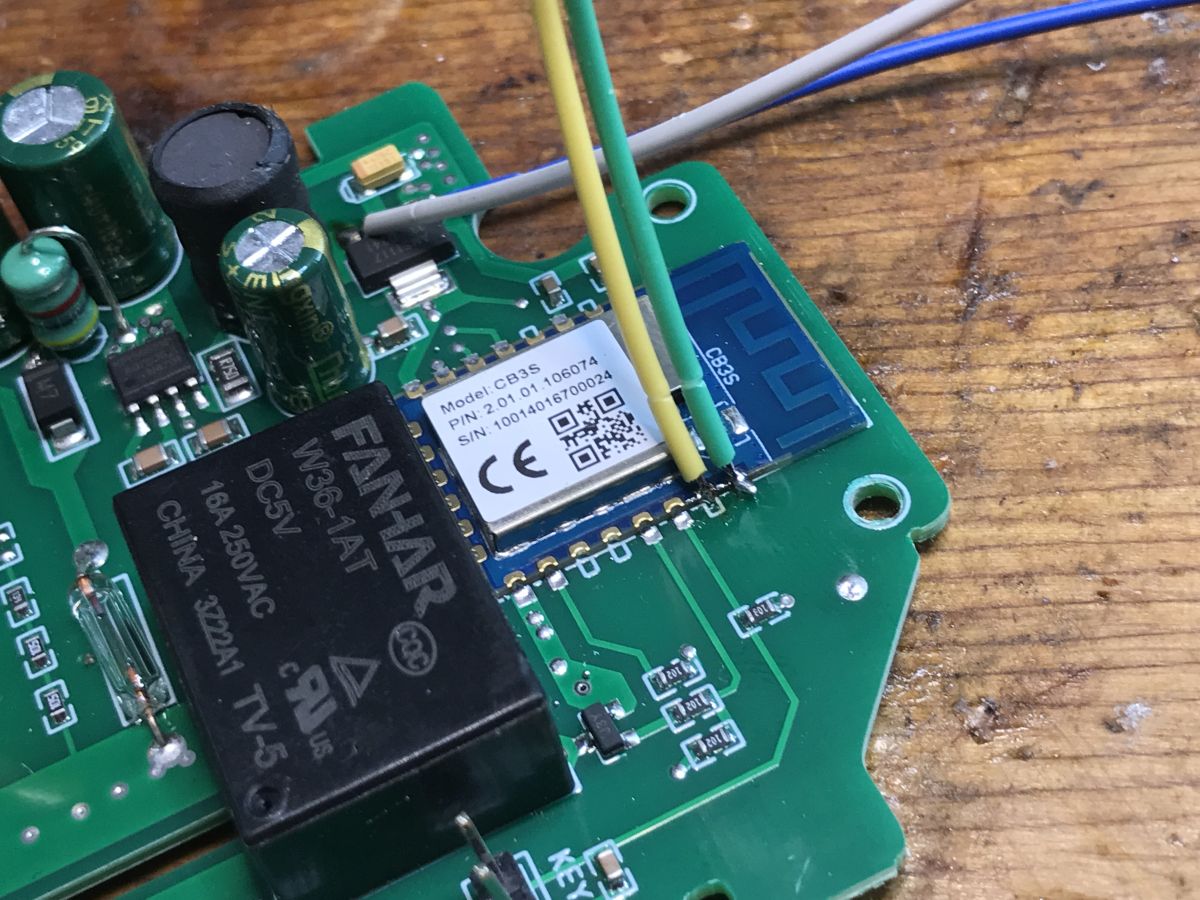
The WiFi module itself is a CB3S - or BK7231N. View from underneath:
 .
.
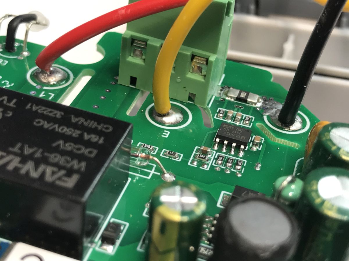
In addition, there is a circuit on the board from energy measurement:
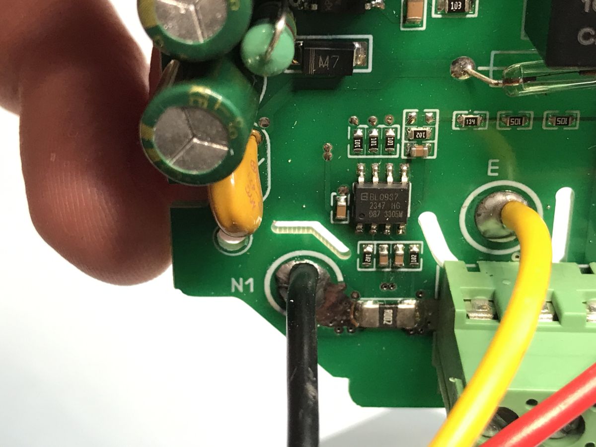 .
.
Now you can change the firmware. .
A USB to UART converter is useful:
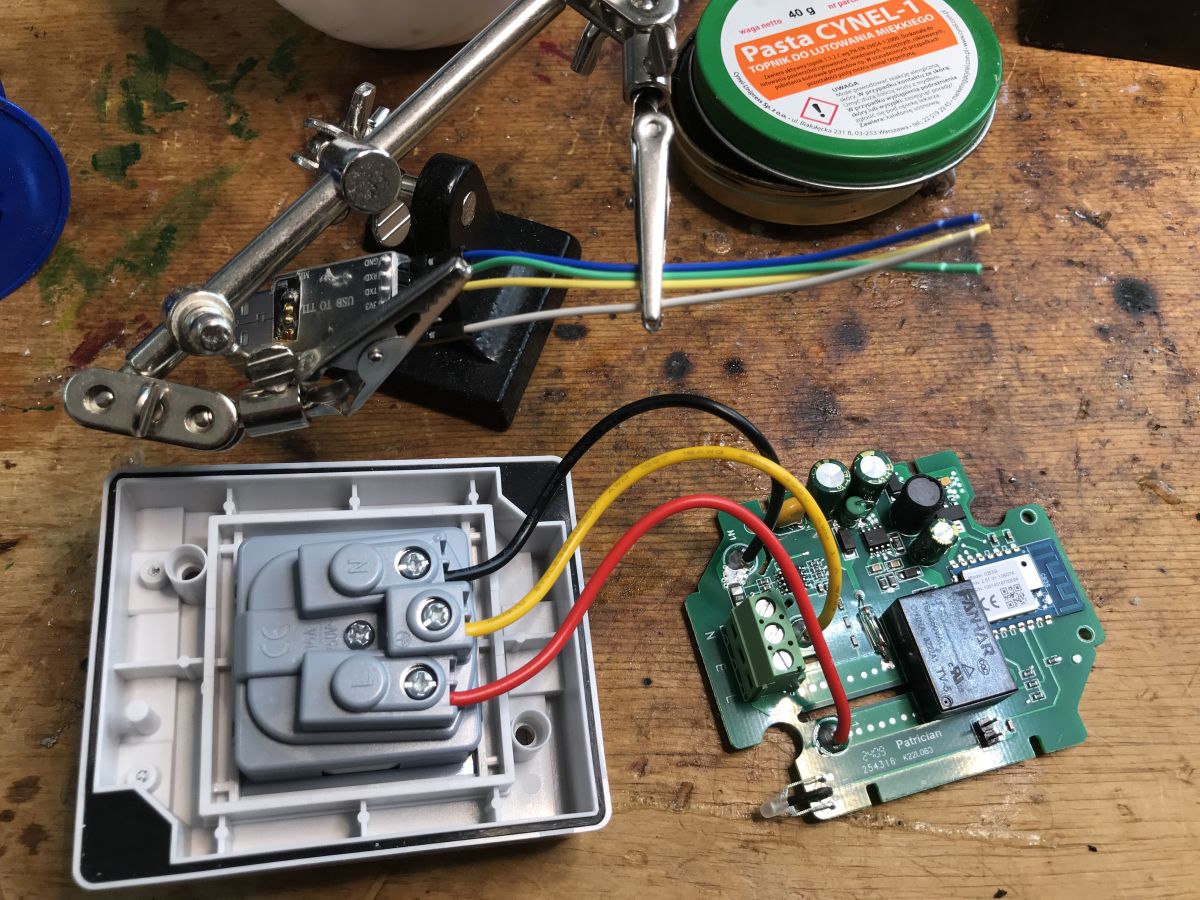 .
.
The WiFi module requires a 3.3V supply, but there is already a 3.3V LDO on the board, so you can feed 5V into its input to get 3.3V. For this you need RX and TX:
 .
.
We program according to the flasher instructions:
https://github.com/openshwprojects/BK7231GUIFlashTool
 .
.
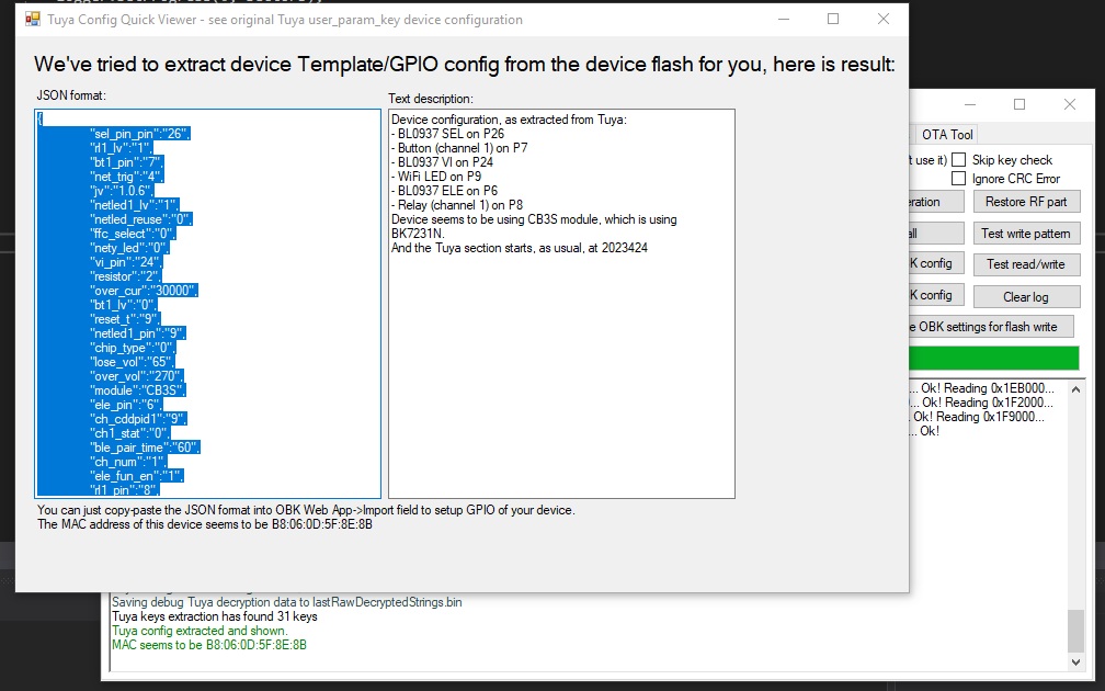
Read the batch first - the flasher will recognise the GPIO configuration this way:
 .
.
Tuya JSON detected:
Code: JSON
Verbal description:
Device seems to be using CB3S module, which is BK7231N chip.
- Relay (channel 1) on P8
- WiFi LED on P9
- Button (channel 1) on P7
- BL0937 ELE on P6
- BL0937 VI on P24
- BL0937 SEL on P26
OBK template:
Code: JSON
Instructions for importing the template:
HA Discovery Instructions:
Other related material on YT Elektroda.com:
https://www.youtube.com/@elektrodacom
Project repository:
https://github.com/openshwprojects/OpenBK7231T_App
For this device, calibration still needs to be done. We connect a 60W bulb, measure exactly what the power consumption is, what voltage, current and enter them with the commands VoltageSet, CurrentSet, PowerSet.
In summary , this was another low cost device offering a simple firmware change. It can be easily disconnected from Tuya and run 100% locally, with Home Assistant, in a fully customisable way.
Some time ago I showed a similar hardware based on ESP8266:
External ATLO-S1IP5-TUYA socket on ESP8266 - interior, firmware change .
Only that it was without energy measurement. Apart from that the construction is quite similar, you can compare on your own.
Do you use this type of external, remote-controlled socket, and if so, how long have such sockets served you faultlessly? .

p.kaczmarek2 wrote 14627 posts with
rating 12646 , helped 655 times.
Been with us since 2014 year.
Comments