 .
.
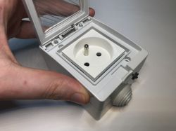
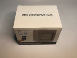
Here I will introduce the ATLO-S1IP5-TUYA external 'French' socket, offering control via WiFi and (emergency) via a button on the case. What sets it apart is that, in the series I tested, it is still based on the ESP8266, so Tasmota can be uploaded. The whole thing is purchasable at about the same price as the internal sockets, which is around £60.
 .
.
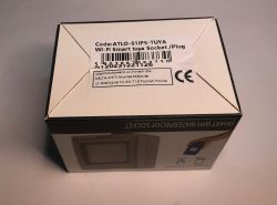
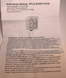
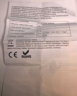
I got such a "manual" in the kit, oddly they don't say anything about pairing? Fortunately I'm changing the firmware anyway.... But you can probably pair by pressing a button.
 .
.
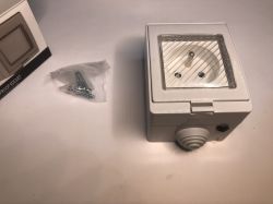
Contents of the kit, as you can see we also get the mounting screws:
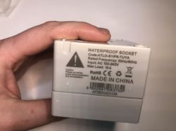
Markings:
 .
.
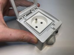
However, I'm interested in the inside of the product, so it's time to unscrew the front panel:
 .
.
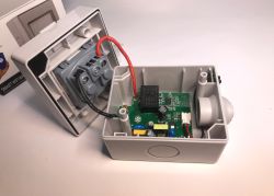
Indeed, the manufacturer has made a basic effort to make this socket a little more resistant to moisture. Both plastic parts are protected by a rubber seal:
 .
.
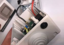
The button from vaping and emergency switching is also protected.
 .
.
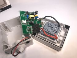
The PCB itself, on the other hand, is ... glued onto something that looks like hot glue.
 .
.
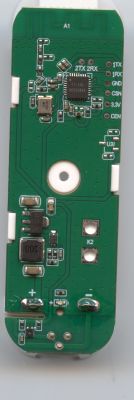
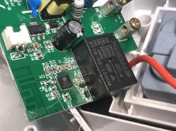
On the board is an ESP8266, or more accurately an ESP8285 - that is, an ESP with 2MB flash memory built in. No external bone is needed. Nor is it here in the form of a module such as the TYWE3S, for example, but the whole thing is on one board.
 .
.
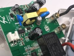
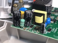
On the same board we also have the power supply section, which is a small flyback power supply. However, there is no non-isolated step-down converter here as in other similar products.
 .
.
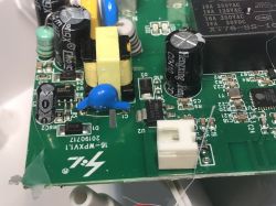
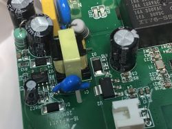
I am all too surprised that the circuit appears to be quite complete. There is a varistor, a filter on the input, a fuse, a Y-capacitor. This is often omitted in cheap products.
 .
.
PCB designation: 20190717 Probably the date of the project...
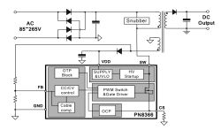
I see there a PN8366, inverter controller with integrated MOSFET transistor.
 .
.
There is also an AMS1117-3.3V on the output, it provides 3.3V for the ESP.
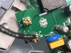
The product, as usual, only cuts off one wire (the phase, if you connect it correctly):
 .
.
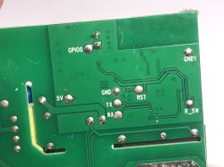
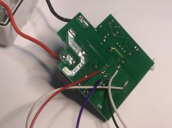
On the bottom of the PCB there are only pads for programming:
 .
.
I will now proceed to change the firmware . I perform the process according to my old topic:
SmartLife switch - test, interior and programming light switch on WiFi .
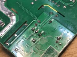
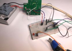
I always apply flux and whiten the pads first, then connect my USB to UART converter with an additional 3.3V LDO:
 .
.
Tip: GPIO0 here is on the button, so basically you don't need to solder this signal, just RX/TX/mass/power. You can hold the button while the power is connected to start flashing mode.
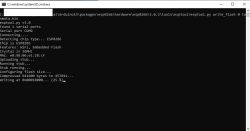
Command to upload Tasmota:
esptool.py write_flash 0 tasmota.bin
 .
.
After disconnecting GPIO0 from ground and rebooting the Tasmota starts:
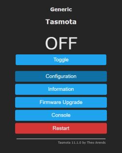
Configuration:
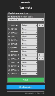 .
.
Short test (web-based testing):
In summary , on the inside it's not as bad as I feared. This is probably one of the better of the Chinese products from this angle. Of course it only cuts off the phase consistently (if you connect it right), but that's already the norm in these products. I don't think I've seen anything in the European market in this range that cuts off both wires.
Changing the firmware was hassle-free, and even if there was a Beken inside instead of ESP, you can always use OpenBeken .
I haven't focused on other aspects as much, but undoubtedly for Home Assistant this slot will come in handy. I recall the related topics:
ESP8266 and Tasmota - WiFi relay control step by step .
Home Assistant tutorial - configuration, WiFi, MQTT, Zigbee, Tasmota .
Do you use these types of external sockets, what experiences have you had with them? Feel free to discuss.
Cool? Ranking DIY Helpful post? Buy me a coffee.


