Today I will present the interior and firmware change of an electrical socket that offers WiFi control and, additionally, measurement of voltage, power and current. I have already described "smart" products with energy measurement, but there was no socket in this style yet. Will I be able to free it from the cloud? What WiFi module is inside? Let's check.
Purchase SWP86-01OG
The product was bought on a Polish auction website for PLN 65:
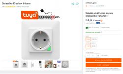
The specific model name may not be available in the offer description, but it is available on the socket itself. There is also something else that catches the eye in this nest - after all, it is not typical for our country, but "schuko". This may cause some serious problems with grounding if, for example, we forget and connect a plug that is not compatible with it!
The product is available in two colors, white and black:
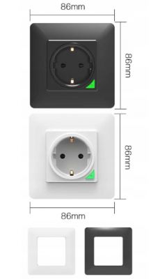
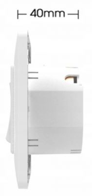
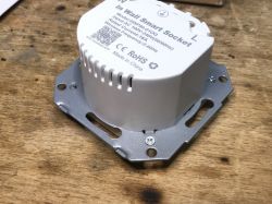
Dimensions as in the picture above, depth shown below:
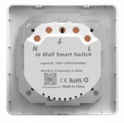
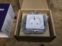
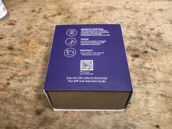
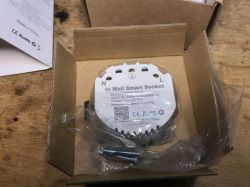
Product packaging:
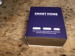
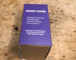
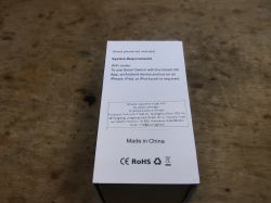
Contents of the set, is something missing?

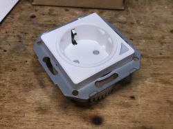
Nothing could be further from the truth, the front panel is simply loose:
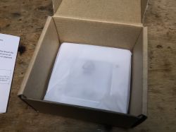
The socket itself with markings:
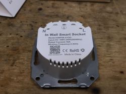
It is worth noting that the screws are also included in the set.
Interior of SWP86-01OG
First, unscrew all the small screws holding the front:
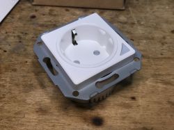
This allows you to free the front, we can see the cable on which the pairing/state change button and LED are connected:
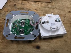
We look inside:
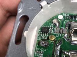
You can immediately see BL0937 - the energy measurement system - along with a low-resistance resistor, a shunt on which the measurement is performed.
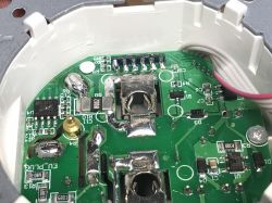
You can also see the legs from the soldered WiFi module (CB2S or WB2S?), the transistor code J3Y, which reliably switches the relay, and the AMS1117-3.3V LDO regulator:
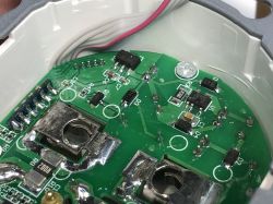
Power is provided by BP2525:
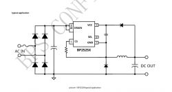
It's just a simple step down, it's not even a flyback power supply, there is no galvanic separation... but no one is likely to push their fingers inside the socket.
Some additional photos:
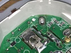
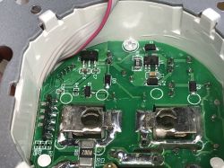
Ok, unscrew the screws and take out the PCB:
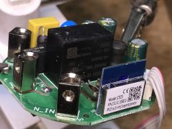
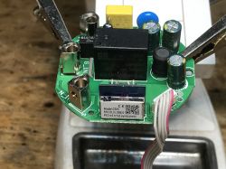
There is a CB2S module, as I thought, BK7231N.
You can also see some input protection, a fuse resistor, a varistor, an anti-interference capacitor:
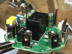
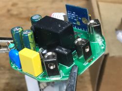
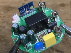
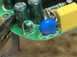
PCB from the bottom:
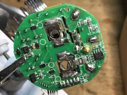
Firmware change
All you need to do is solder the CB2S (or WB2S) pins, the pins are in the network, everything in accordance with:
https://github.com/openshwprojects/BK7231GUIFlashTool
Flux, plus a little lead binder would make soldering better and you can easily get to it through four wires:
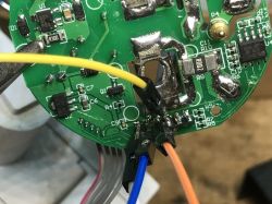
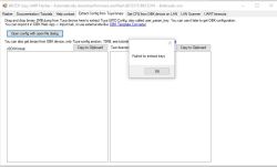
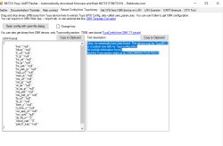
There remains the issue of GPIO. Here is the schedule:
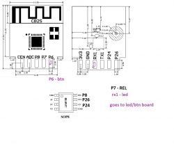
And the template:
Code: JSON
Ready. You still need to calibrate the energy measurement using the VoltageSet/CurrentSet/PowerSet commands, as in Tasmota , and then you can use this device 100% locally, without potential manufacturer surveillance, and connect it conveniently with Home Assistant.
Summary
This product is not as expensive as it may seem, especially since it is available on our national auction site, with the possibility of free smart delivery to a parcel locker. Energy measurement certainly increases its usefulness. It is also worth remembering that the button on the housing also allows you to control it, so in the event of a problem with WiFi, we are not completely cut off from control.
After changing the firmware, you can also script OpenBeken so that another product (e.g. a light switch) controls this socket locally, just add one line with the button event handler (e.g. double-click), sending an HTTP GET event with the POWER TOGGLE command to the IP of the socket . All without the use of the cloud and even without Home Assistant.
Details about firmware here:
https://github.com/openshwprojects/OpenBK7231T_App
And in the documentation section:
https://github.com/openshwprojects/OpenBK7231T_App/blob/main/docs/README.md
Does any reader have this type of "smart" sockets at home?
Cool? Ranking DIY Helpful post? Buy me a coffee.


![[BK7231N/CB2S] SWP86-01OG energy measurement socket [BK7231N/CB2S] SWP86-01OG energy measurement socket](https://obrazki.elektroda.pl/2179898700_1701373479_thumb.jpg)
![[BK7231N/CB2S] SWP86-01OG energy measurement socket [BK7231N/CB2S] SWP86-01OG energy measurement socket](https://obrazki.elektroda.pl/7197422700_1701371498_thumb.jpg)
