logo elektroda
logo elektroda
X
logo elektroda

Mycket Smart Outdoor Socket PE-01E IP44 with energy measurement

p.kaczmarek2 5220 20
ADVERTISEMENT
Treść została przetłumaczona polish » english Zobacz oryginalną wersję tematu
  • Mycket Smart Outdoor Socket PE-01E IP44 with energy measurement
    I will present here the interior of a very cheap "outdoor" Tuya socket, which also offers energy measurement. Here I will provide information on how to change its firmware and show the ready configuration OpenBeken for this slot. I will show how to run the statistics system for this socket in OBK and use the Home Assistant Discovery. This socket has a WB2S WiFi module inside and a BL0937 chip for energy measurement OpenBeken Support.


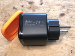
    Mycket Smart Socket PE-01E IP44
    The socket is quite distinctive, I think it will be easy to recognize, even though I won't include screenshots from the listing here - I just got them from its importer who supports OpenBeken's development.
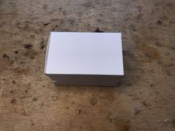
    Here is the box:
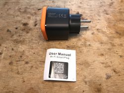
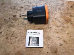
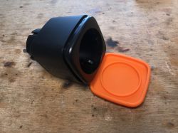
    Mycket Smart Outdoor Socket PE-01E IP44 with energy measurement Mycket Smart Outdoor Socket PE-01E IP44 with energy measurement
    Mycket Smart Outdoor Socket PE-01E IP44 with energy measurement Mycket Smart Outdoor Socket PE-01E IP44 with energy measurement
    Mycket Smart Outdoor Socket PE-01E IP44 with energy measurement Mycket Smart Outdoor Socket PE-01E IP44 with energy measurement


    The interior of the PE-01E, loading the charge
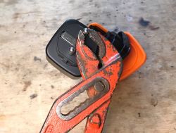
    Unfortunately, it is not a Blitzwolf BW-SHP6 that is easy to disassemble and assemble. It is also not simply a clone of LSPA9. The cover can be removed, but then there is a problem with the pins:
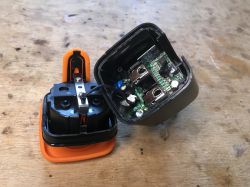
    Mycket Smart Outdoor Socket PE-01E IP44 with energy measurement
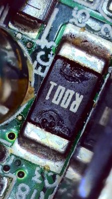
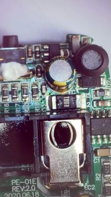
    You can see the energy measurement system - BL0937.
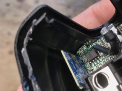
    Mycket Smart Outdoor Socket PE-01E IP44 with energy measurement
    Mycket Smart Outdoor Socket PE-01E IP44 with energy measurement
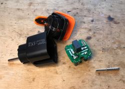
    The pins do not twist. They are soldered. Unfortunately...
    The PCB was removed, but at what cost:
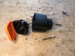
    Mycket Smart Outdoor Socket PE-01E IP44 with energy measurement Mycket Smart Outdoor Socket PE-01E IP44 with energy measurement
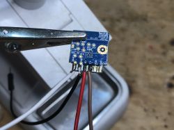
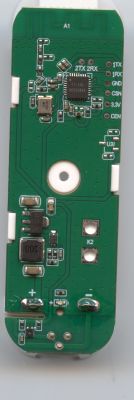
    There is a WB2S module inside. I took it out for programming:
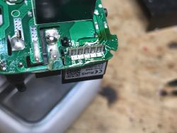
    Mycket Smart Outdoor Socket PE-01E IP44 with energy measurement Mycket Smart Outdoor Socket PE-01E IP44 with energy measurement
    I only connect VDD, GND, RX and TX. USB to UART adapter in 3.3V mode. VDD is 3.3V. bkWriter is able to program this module. To perform a RESET, I cut off the power.
    Just like, among others here:
    Electric socket with LSPA9 energy measurement - we program our own firmware
    We take bins from here:
    https://github.com/openshwprojects/OpenBK7231T_App/releases

    Pairing with Tuya
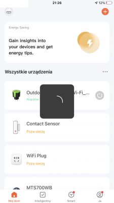
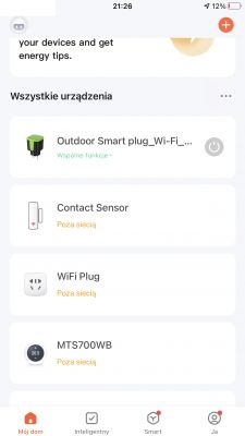
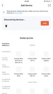
    The purpose of the game is to change the load, but I did a short test with the Tuya app anyway. Let's see how Tuya sees this nest ...
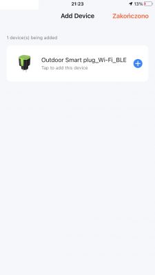
    Mycket Smart Outdoor Socket PE-01E IP44 with energy measurement Mycket Smart Outdoor Socket PE-01E IP44 with energy measurement Mycket Smart Outdoor Socket PE-01E IP44 with energy measurement Mycket Smart Outdoor Socket PE-01E IP44 with energy measurement
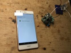
    I steamed them like this:
    Mycket Smart Outdoor Socket PE-01E IP44 with energy measurement

    OpenBeken configuration
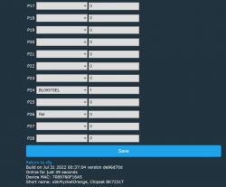
    To configure the firmware after the change, we need to know what pins are the button, relay and signals from BL0937 on.
    This is shown in the screenshot below:
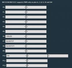
    Mycket Smart Outdoor Socket PE-01E IP44 with energy measurement
    Mycket Smart Outdoor Socket PE-01E IP44 with energy measurement
    Additionally, the energy measurement should be calibrated in accordance with:
    https://www.elektroda.pl/rtvforum/topic3887748.html
    This socket additionally has a separate LED diode, which can be used either as a WiFi status LED or connected to the relay status (with _n if we want with negation).


    Energy consumption statistics
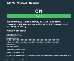
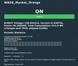
    It is worth adding that thanks to the latest updates, OpenBeken also counts how much we used in watt hours. It always counts how much we have used in total, but it can also count the consumption in the last period of time (e.g. in an hour). This can be run through a console command, which we enter, for example, in 'Short startup command':
    
    SetupEnergyStats [enable] [sample_time] [sample_count]
    SetupEnergyStats 1 60 60
    

    sample_time - how many times it saves the measurement in seconds
    sample_count - how many samples we save in total
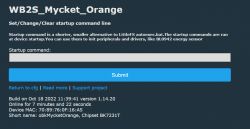
    Mycket Smart Outdoor Socket PE-01E IP44 with energy measurement
    Here is the view from the panel:
    Mycket Smart Outdoor Socket PE-01E IP44 with energy measurement
    Little later:
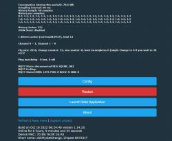
    Mycket Smart Outdoor Socket PE-01E IP44 with energy measurement
    Mycket Smart Outdoor Socket PE-01E IP44 with energy measurement

    Pairing with Home Assistant
    There are already two ways at the moment.
    Method 1 - Home Assistant Discovery:
    Just set up MQTT. Then we open "Generate Home Assistant CFG" and there we have:
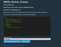
    Mycket Smart Outdoor Socket PE-01E IP44 with energy measurement
    I emphasize - recently the Discovery also automatically adds the measurement fields to the HA, i.e. voltage, power, etc. You do not have to do it manually anymore.
    Method 2 - handwriting Yaml like in this topic:
    https://www.elektroda.pl/rtvforum/topic3887748.html

    Summary
    Those slightly more budgetary power metering sockets, the Mycket Smart Socket PE-01E, NAS-WR01W and NAS-WR07W models are a bit more difficult to take apart. I had problems with each of them. I finally put this Mycket together, but I had to figure out how to solder the pins of the plug so that they would stick firmly. Luckily I had a soldering iron strong enough and the pins returned to their place (because yes, they were soldered to the pads by the manufacturer).
    I have already prepared a tuya-cloudcutter profile for this socket, including the pull request:
    https://github.com/tuya-cloudcutter/tuya-clou...mmit/41f82d20b0e4d450ec6d788441e612910740dc32
    Tuya-cloudcutter will allow you to change the load of this socket remotely - without opening the housing. Details can be found in their repository.

    Cool? Ranking DIY
    Helpful post? Buy me a coffee.
    About Author
    p.kaczmarek2
    Moderator Smart Home
    Offline 
    p.kaczmarek2 wrote 11930 posts with rating 9987, helped 572 times. Been with us since 2014 year.
  • ADVERTISEMENT
  • #2 20244059
    Karol966
    Level 31  
    p.kaczmarek2 wrote:
    energy measurement system - BL0937.
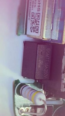
    In this socket, as in the documentation, there is a 1mOhm shunt?
    https://datasheet.lcsc.com/lcsc/1811151441_BL-Shanghai-Belling-BL0937_C94616.pdf So the equipment is deadly to fumble around at work, I don't follow the topic but it's probably 99.99% of cases that there is a shunt instead of a CT.
    What is the resolution of the current / power measurement?
  • #3 20386417
    dbizarro
    Level 1  
    Karol966 wrote:
    p.kaczmarek2 wrote:
    energy measurement system - BL0937.
    In this socket, as in the documentation, there is a 1mOhm shunt?
    https://datasheet.lcsc.com/lcsc/1811151441_BL-Shanghai-Belling-BL0937_C94616.pdf So the equipment is deadly to fumble around at work, I don't follow the topic but it's probably 99.99% of cases that there is a shunt instead of a CT.
    What is the resolution of the current / power measurement?


    Here you have some pics....

    Mycket Smart Outdoor Socket PE-01E IP44 with energy measurement Mycket Smart Outdoor Socket PE-01E IP44 with energy measurement
    Mycket Smart Outdoor Socket PE-01E IP44 with energy measurement Mycket Smart Outdoor Socket PE-01E IP44 with energy measurement
  • #4 20790915
    ThWi
    Level 2  
    Hi

    may I ask how did you solve this:

    "Luckily I had a soldering iron strong enough and the pins returned to their place"

    Because I believe if i use a strong enough soldering iron i will will smell the plastic cover where the pins are in? Furthermore, how can I be sure that solder is successful placed because I cant see it anymore the cover hides it?

    Can you give more details how you solved the problem?

    Tnx in advance

    Thomas
  • ADVERTISEMENT
  • #5 20791696
    p.kaczmarek2
    Moderator Smart Home
    Hello @ThWi, welcome to Elektroda.
    There is no magic in soldering, I just mixed some Pb solder with the original one, added some flux, then used solder wick to remove the old solder mix, then readded new Pb solder (because of the low melting point of the mix), melted it well and then made the joint.

    Futhermore, in this particular case, I think I soldered pins first, then I put on the case, but I may be wrong. It was long time ago already.
    Helpful post? Buy me a coffee.
  • #6 20791775
    ThWi
    Level 2  
    Hello

    thanks for your feedback.

    I think I got it, you right soldering isn't a big issue.

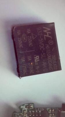
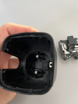
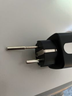
    But the pins shout be inside the cover (moved from buttom). May be I'm wrong but it might be you reamed the hole for the pin? I've no clue how it could work? Please have a look to the pictures? I know is not a mycket because I have GreenSun Plugs, but it is exact the same only, vendor and color are different ;-)

    thanks for your assistant.

    ThWi Interior of a plastic casing with two protruding pins and a disassembled electronic component. Two-pin electrical plug on a grey surface.
  • #7 20791960
    p.kaczmarek2
    Moderator Smart Home
    Ah, I see what you are asking for, I can see the problem, but I don't remember how I solved it.
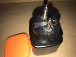
    I can show you how socket looks now:
    Black and orange smart plug adapter with three prongs. Close-up view of a black plug with two metal pins.
    I can see that I glued the pins.... but I dont remember why.

    Btw, here's a Tuya JSON for this device:
    Code: JSON
    Log in, to see the code
    Helpful post? Buy me a coffee.
  • #8 20792312
    ThWi
    Level 2  
    Hi,

    great, this points me out! I can see the glue means you drilled out the cover holes to put the pins from "inside" through the hole. That's what I expected.

    Yes, I know the tyua json, but I have 43 devices (WBS and EPS Chips) migrated from tuya to tasmota (brennenstuhl out and in door, also antela devices). Only this 5 from GreenSuns are not solved, but now its ongoing. Soldering and gluing is my next job now. ;-)

    My way is tasmota -> mqtt -> node-red -> influxdb -> grafana it works fine.

    anyway ... many many thanks for your assistant.

    One more question beside: the main reason why i moved from tuya to tasmota, I did't find a easy way from tuya-api to a influxdb. I searched for docker as well python script, but success. The tuya exporter to promsql was not sufficient to me. May be you have an other hint?

    Tnx in advance

    regards ThWi
  • #9 21100299
    tomik67
    Level 12  
    Hi.

    I recently purchased a similar device to the one described here:

    [url=]https://www.aliexpress.com/gcp/300000512/nnmixupdatev3?spm=a2g0o.productlist.main.7.129ftQMhtQMhjA&productIds=1005006437113170&pha_manifest=ssr&_immersiveMode=true&disableNav=YES&channelLinkTag=nn_newgcp&sourceName=mainSearchProduct&utparam-url=scene%3Asearch%7Cquery_from%3A[/url]

    I tried to use the cloudcutter with the profile from you to avoid unsealing by stripping, unfortunately this does not work.
    Is it possible that the profile has changed or they have patched the device ?
    Logs attached.
  • ADVERTISEMENT
  • #10 21100396
    p.kaczmarek2
    Moderator Smart Home
    What version of Tuya's firmware?
    Helpful post? Buy me a coffee.
  • #11 21100528
    tomik67
    Level 12  
    Main module V1.1.15
    Other type V1.0.5
  • #12 21100547
    p.kaczmarek2
    Moderator Smart Home
    Quote:

    Are all devices supported by Tuya-cloudcutter?
    Currently there are some patched BK7231N devices on the market, they can be recognized by firmware versions:
    - 1.1.2 oem_bk7231n_garage_door (Tuya Generic QS-WIFI-C03 Gate Opener Switch)
    - 1.1.12 oem_bk7231n_plug (Nous A1, Tuya Generic LSPA9 Smart Plugs)
    - 1.1.15 oem_bk7231n_plug (various smart plugs)
    - 1.3.3 oem_bk7231n_dctrl_switch (HomeMate 4 Node Smart Switch)
    - 1.3.8 oem_bk7231n_control_switch (ColoRock CR-MINI-V2 Mini Smart Relay)
    - 1.3.10 oem_bk7231n_control_switch (OXT_SWT10 240V 150W 5A Dry Contact Relay)
    - 1.5.10 oem_bk7231n_light_ty (Tuya Generic Light, TuyaOS 3.3.2)
    - 2.0.15 oem_bk7231n_strip_ty (Anko Sunset Light)

    Version 1.1.15 from smart plugs is not susceptible to flashing via WiFi
    Helpful post? Buy me a coffee.
  • ADVERTISEMENT
  • #13 21100581
    tomik67
    Level 12  
    I thought this only applied to the N version
    I understand that there is no possibility of undoing the firmware.
  • #14 21100589
    p.kaczmarek2
    Moderator Smart Home
    Actually, you didn't give any information in your question whether you have a device on T or on N, but in my experience Tuya uses them interchangeably. In any case, this soft is listed as zpatchable. You will need to take the case apart and solder.
    Helpful post? Buy me a coffee.
  • #15 21100993
    tomik67
    Level 12  
    This is sad, I had hoped not to dismantle the plugs which should be tight.
    I did not write what type of module because to find out it is necessary to dismantle which I wanted to avoid.
  • #16 21101011
    p.kaczmarek2
    Moderator Smart Home
    Now I understand, so you have specifically this version, the "external" one? Well it's hard, it's going to get worse and worse, they probably don't even produce devices on the old software anymore.

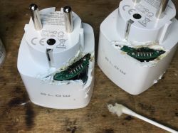
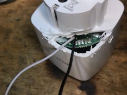
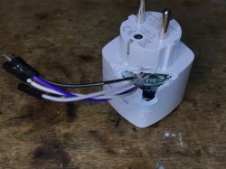
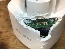
    What method do you use to dismantle it now? On this particular model there is a problem with removing the PCB at all. Apparently it can also be done like this:
    Two white, damaged smart plugs by BLOW with exposed internal electronics. Close-up of a damaged electrical device with a visible opening through which wires and a PCB are protruding. View of a modified electrical plug with exposed wires and PCB. Damaged plastic device casing with visible interior and PCB. Damaged plastic device casing with visible interior and PCB. but that might be even worse way in terms of tightness, because how to fix it afterwards..
    Helpful post? Buy me a coffee.
  • #17 21101109
    tomik67
    Level 12  
    The latter method is a bit axe-like, for ordinary plugs I've seen a way with a frame, but with IP44 it probably won't work, from your photos it looks like they made a "socket" in the deep part of the housing for the "tongue" in the smaller part, for the sake of tightness, to which they added glue or welding. it's obvious that they put a lot of care into tightness. It's going to be hard to keep the aesthetics as such after the battle. I'm still thinking about how to bite it.
  • #18 21114565
    tomik67
    Level 12  
    I managed to open this plug harmlessly.
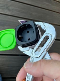
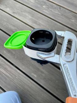
    Inspired by the frame idea, I used a vise for the first plug and a hydraulic spanner for the other two.
    In both cases, use spacers of hard cardboard or thin plastic to avoid unsightly damage to the housing.
    The imprints visible in the photos are the remnants of previous unsuccessful attempts to open the socket.

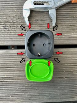
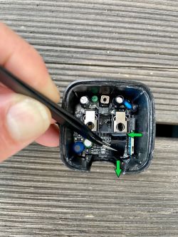
    1 Using a plumber's spanner through the spacer, squeeze the plug at the top of the housing at the points marked by the arrows repeatedly with varying force and feel, diagonally across the plug also.
    With enough pressure you should hear the cracking of the glue points of the lower and upper housing, after which you should feel that the upper part is loose, if it still holds something, with up-down, left-right movements eliminate the last points of resistance.


    Example of using a pipe wrench to open a plug. Electrical plug held in a pipe wrench with a cardboard spacer. The image shows a disassembled plug and a pipe wrench on a wooden surface. Red and black arrows indicate pressure points on the black casing. .


    2. after freeing the top of the case, unscrew the earth wire


    Opened plug housing with visible electronics inside. .


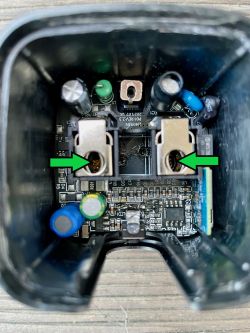
    3. then gently cut the silicone with which the cover of the PCB mounting screw is glued and slide out the freed cover


    Opened plug housing showing internal components with highlighted arrows. .


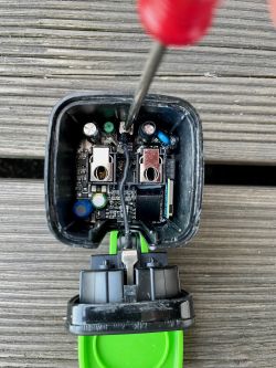
    4 This gives us access to the two mounting screws securing the PCB to the chassis located in the plug pin sockets, we pull out the PCB


    Inside view of a plug housing with visible electronic components and marked arrows. .


    Assemble everything in reverse order.
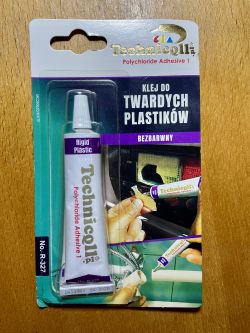
    To get IP44 splash proof again you need to glue the plug together, I used hard plastic glue for this Technicqll Polychloride Adhesive 1 which melts the plastic at the connection point for better effect and tightness and I left the compressed housing for 12 hours for the glue to cure. Clean the case tongue and groove before gluing.

    Packaging of Technicqll adhesive for hard plastics .


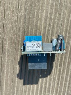
    Of the three plugs received in one delivery only one had a WB2S module, the others had CB2S, the PCB in all was the same.


    PCB with CB2S module and CE markings on a wooden surface. .

    Module plug pins WB2S ..:

    - BL0937 SEL on P24
    - Button (channel 1) on P10
    - BL0937 VI on P8
    - WiFi LED on P6 alternatively if LED is to indicate relay status and not WiFi status - LED_n (channel 1) on P6
    - BL0937 ELE on P7
    - Relay (channel 1) on P26

    json:
    {
       "sel_pin_pin":"24",
       "rl1_lv":"1",
       "bt1_pin":"10",
       "net_trig":"1",
       "jv":"1.1.5",
       "netled1_lv":"0",
       "bt1_type":"0",
       "nety_led":"2",
       "vi_pin":"8",
       "resistor":"1",
       "over_cur":"17000",
       "bt)":"Bgw_wsm1_lv",
       "reset_t":"3",
       "netled1_pin":"6",
       "chip_type":"0",
       "lose_vol":"85",
       "over_vol":"270",
       "module":"WB2S",
       "ele_pin":"7",
       "ch_cddpid1":"9",
       "ch1_stat":"2",
       "rl1_type":"0",
       "ch_num":"1",
       "rl1_pin":"26",
       "netn_led":"2",
       "vol_def":"0",
       "ch_dpid1":"1",
       "sel_pin_lv":"1",
       "crc":"74",
       "}":"Bgw_dikey",
       "auth_key":"BMAsF1AVfp59aRH1WodZjh6ZfV8ErvZ7",
       "bv":"40.00",
       "pv":"2.2",
       "lpv":"3.3",
       "pk":"keym9qkuywghyrvs",
       "firmk":"keym9qkuywghyrvs",
       "cadv":"0nc_tp",
       "ssid":"null",
       "passwd":"null",
       "md":"0",
       "random":"0",
       "wfb64":"1",
       "stat":"0",
       "token":"null",
       "region":"null",
       "reg_key":"null",
       "dns_prio":"00{uuid",
       "psk_key":"RsizkoOhBX2ZgKeEoblLASGpmHLeDLwHeHnCR",
       "ap_ssid":"SmartLife",
       "ap_passwd":"null",
       "country_code":"CN",
       "bt_mac":"null",
       "bt_hid":"null",
       "prod_test":"false }1.0.2",
       "cdv":"1.0.0",
       "dev_swv":"1.3.5",
       "s_id":"null",
       "dtp":"0",
       "sync":"0",
       "attr_num":"0",
       "mst_tp_0":"0",
       "mst_ver_0":"null",
       "mst_tp_1":"0",
       "mst_ver_1":"null",
       "mst_tp_2":"0",
       "mst_ver_2":"null",
       "mst_tp_3":"0",
       "mst_ver_3":"null",
       "dminfo_name":"null",
       "dminfo_code":"null",
       "dminfo_report_code":"null",
       "dminfo_sn":"null "
    }
    .


    Plug pins with module CB2S :

    - BL0937 SEL on P24
    - Button (channel 1) on P10
    - BL0937 VI on P6
    - WiFi LED on P8 alternatively if LED is to indicate relay status and not WiFi status - LED_n (channel 1) on P8
    - BL0937 ELE on P7
    - Relay (channel 1) on P26

    json:
    
    {
       "sel_pin_pin":"24",
       "rl1_lv":"1",
       "bt1_pin":"10",
       "net_trig":"1",
       "jv":"1.0.5",
       "netled1_lv":"0",
       "netled_reuse":"1",
       "bt1_type":"0",
       "ffc_select":"0",
       "vi_pin":"6",
       "resistor":"1",
       "over_cur":"17000",
       "bt1_lv":"0",
       "reset_t":"3",
       "netled1_pin":"8",
       "chip_type":"0",
       "lose_vol":"80",
       "over_vol":"270",
       "module":"CB2S",
       "ele_pin":"7",
       "ch_cddpid1":"9",
       "ch1_stat":"2",
       "rl1_type":"0",
       "ch_num":"1",
       "ele_fun_en":"1",
       "rl1_pin":"26",
       "vol_def":"0",
       "ch_dpid1":"1",
       "sel_pin_lv":"1",
       "crc":"30",
       "bv":"40.00",
       "pv":"2.2",
       "lpv":"3.4",
       "pk":"keyjup78v54myhan",
       "firmk":"keyjup78v54myhan",
       "cadv":"05",
       "cdv":"1.0.0",
       "dev_swv":"1.1.15",
       "s_id":"null",
       "dtp":"0",
       "sync":"0",
       "attr_num":"1",
       "mst_tp_0":"9",
       "mst_ver_0":"1.1.15",
       "mst_md5_0":"null",
       "mst_tp_1":"0",
       "mst_ver_1":"null",
       "mst_md5_1":"null",
       "mst_tp_2":"0",
       "mst_ver_2":"null",
       "mst_md5_2":"null",
       "mst_tp_3":"0",
       "mst_ver_3":"null",
       "mst_md5_3":"null "
    }
    .
  • #19 21114675
    p.kaczmarek2
    Moderator Smart Home
    Thank you for the comprehensive presentation, until I checked myself if my Mycket has hidden screws, but I don't see anything like that.... I know about the hidden screws on the Blitzwolf, but my PE-01E doesn't seem to have them.
    Helpful post? Buy me a coffee.
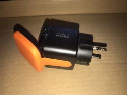
  • #20 21115745
    tomik67
    Level 12  
    As you can see from this thread, every now and then the name of this socket changes, as well as the mounting method, apparently previously there were no screws but soldering.
    By the way, in the examples of scripts for OBK I found one that allows you to dynamically change the mode of the LED, it flashes when it searches for a WiFi connection, i.e. WiFiLED mode, once connected it already works as an LED, i.e. relay state...:

    alias mode_wifi setPinRole 6 WifiLED_n
    alias mode_relay setPinRole 6 LED_n
    
    // at reboot, set WiFiLEd
    mode_wifi
    // then, setup handlers
    addChangeHandler WiFiState == 4 mode_relay 
    addChangeHandler WiFiState != 4 mode_wifi 
    .

    Of course, for WB2S change setPinRole to 8
  • #21 21127051
    tomik67
    Level 12  
    And here's a curiosity, the same socket with a different name, also distributed in Poland and recommended on the Tasmota forum...:

    Link .

Topic summary

The discussion revolves around the Mycket Smart Outdoor Socket PE-01E IP44, which features energy measurement capabilities and is compatible with OpenBeken firmware. Users share insights on modifying the socket's firmware, including soldering techniques for pin connections and troubleshooting issues related to device disassembly. The conversation highlights the use of the WB2S WiFi module and BL0937 chip for energy measurement, as well as the challenges faced when attempting to flash the device with custom firmware. Participants also discuss the compatibility of various Tuya firmware versions and the methods for safely opening the socket without damaging its waterproof integrity.
Summary generated by the language model.
ADVERTISEMENT