Remote-controlled "smart" strip with USB C and QC? SL-PS27 - test, interior, Home Assistan
 .
.
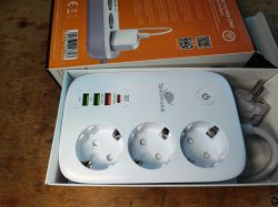
I invite you to a short test, presentation of the interior and change of firmware of the "intelligent" power strip model SL-PS27. By the way, we will also find out what is the "laptop overload protection" that this power strip supposedly offers.
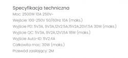
We will start by purchasing the power strip. It costs around 100 zł. For this amount we get 3 mains sockets and 4 USB sockets and one mains switch. What does the seller say about the product?
 .
.
No mention of anti-surge I noticed, but this bit is interesting:
 .
.
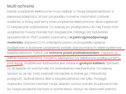
To quote:
Quote:..
In addition, a number of safety systems have been incorporated into the design of the device. Such as overload protection. This will ensure the complete safety of your laptop or phone connected to the power strip.
f1
What's the point here? About the fact that in Tuya you can set a timer that will switch off charging after a certain amount of time? But for what?
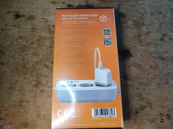
So let's see what you get after purchase:
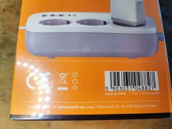
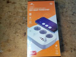
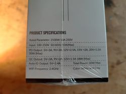
 .
.
Contents:
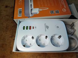
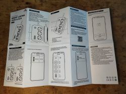
Instructions;
 .
.
Here we have four remote control channels - three network sockets and collectively all USB.
I skip the tests with the Tuya app, this has been tested many times.
We take a look inside, a special screwdriver will come in handy:
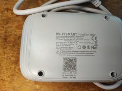
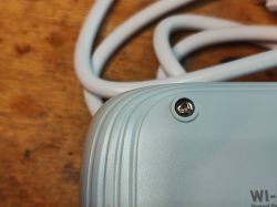 .
.
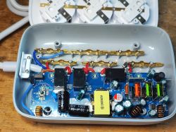
Remove the cover:
 .
.
The first thing that catches the eye is the presence of an NTC starting thermistor- better than nothing. Secondly, I also see here that there is no normal on/off switch, this button on the casing only gives the WiFi module the signal that all four relays need to be switched off....
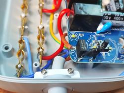
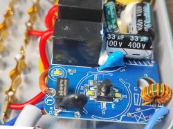
Well, and you can see (as usual) the empty space for the varistor. Well, because why protect against surges?
The power supply itself is probably in flyback topology:
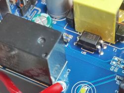
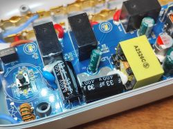 .
.
This time it's not the usual budget PSR (Primary Side Regulation), there's an optocoupler here, a classic 817, for feedback from the secondary side.
And then there's the WiFi module:
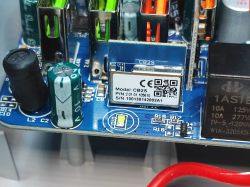
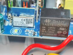 .
.
OpenBeken can be uploaded on the CB2S, but let's look at the rest of the board first.
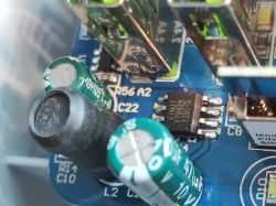
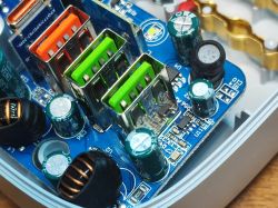
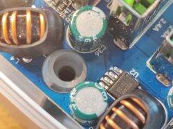 .
.
What is this MOSFET? Maybe it's what the WiFi module uses to switch on the USB outputs?
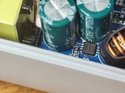 .
.
On the USB side I see components suggesting another inverter. This is rather as expected, as QC attached and e.g. 9V on one port should not switch on 9V on the other ports, plus not all ports here have QC. Unfortunately the FT8828 datasheet note was not found, maybe someone will have more luck?
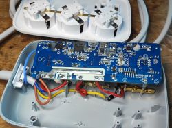 .
.
There's still the bottom of the PCB left.... On which there are quite a few components. You can see the rectifier bridge, then the main inverter controller, then (on the secondary side) a component which I suspect to be a synchronous rectifier (instead of a Schottky diode) and then I can still see the 3.3V supply for the WiFi module.
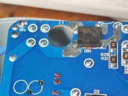
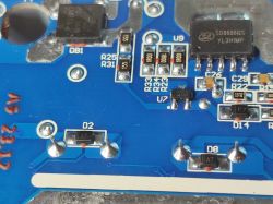
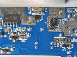 .
.
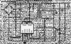
So the inverter is built here based on the SD8666QS. I haven't seen one realised using an optocoupler for a long time:
 .
.
Power up to 36W, this would coincide with the description, as you still need to power the WiFi module and relays too.
 .
.
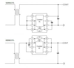
Next we have the SD8525H, just as I thought, a synchronous rectifier:
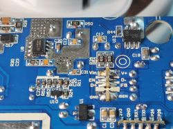
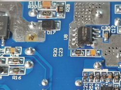 .
.
Diagram:
 .
.
U1 is AMS1117-3.3V - LDO supplying the WiFi module:
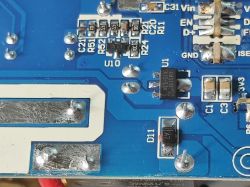 .
.
Here we undoubtedly have a circuit that "reports" the charger to the phones, I wrote about this in more detail in the topic:
Two-port USB charger that accelerated the charging of my iPhone
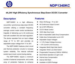
The NDP1340 remains:
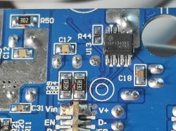 .
.
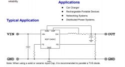
Buck inverter controller. So much for step down:
 .
.
From this it would appear that the main power supply generates the higher voltage and only the NDP1340 gives 5V for the USB?
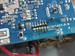
PCB designation: SCW3451 REV1.0.
I have already seen this product in REV1.5, then I can now compare it with the 1.0 version.
[CB2S/BK7231N] LDNIO SEW3452 USB QC extender/charger strip .
Firmware change .
As per the flasher's instructions:
https://github.com/openshwprojects/BK7231GUIFlashTool
and with Elektroda's videos for BK7231:
https://www.youtube.com/playlist?list=PLzbXEc2ebpH0CZDbczAXT94BuSGrd_GoM
CB2S I soldered out:
 .
.
I powered via an external 3.3V LDO:
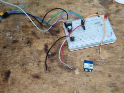
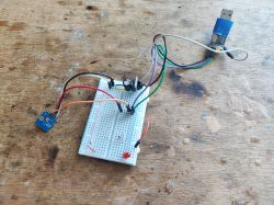
BK7231 easy gui flasher self-detected configuration:
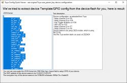
JSON Tuya:
Code: JSON
OBK template:
Code: JSON
The list can now be paired with HA:
Current and charging capacity test .
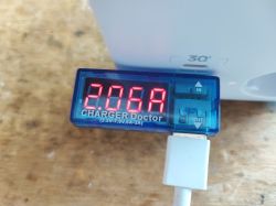
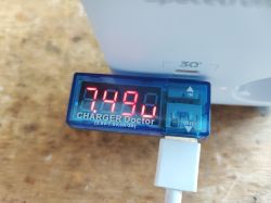
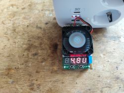
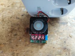
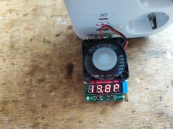
20W at 5V I am able to draw. With QC I was able to attach 7.5V at 2A for my phone, but I did not test with QC Trigger:
 .
.
Summary .
This strip is very similar to the LDNIO SEW3452. only here it is PCB version 1.0 and there it was 1.5. The GPIO template for the WiFi module for both products is consistent, even though the PCB version is different. Probably other strips looking the same from the outside may also have a similar template, so if you want to order something to work either with Tuya or 100% locally with Home Assistant (after a firmware change) it's rather not worth delaying. I've already flashed a few similar pieces and these strips do well in 'local' operation.


Comments
Hi, Very cool and insightful review. Thank you. I'm considering buying such a strip and would like to ask how do you rate the 230V part (sockets, wires, tracks on the board, relays)? I infer from the... [Read more]