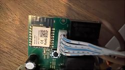
As sold in the Action stores (NL, Dec 2024). First some images:


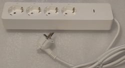
The device can be successfully used with OpenBeken, but requires some DIY skills to open the housing without damage.
BIG FAT WARNING: the electronics inside the power strip are directly connected to the 230V mains lines, without any isolation!
Keep the mains plug disconnected during the whole operation!
First, remove the 8 rubber feet (they pull out very easily):
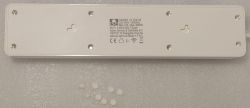
Next, you'll find screws with a completely flat head surface. For the rest, they are normal self-tapping plastic screws:
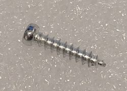
So, how to get them out? As first attempt, I tried to drill them out. This ruined the plastic housing around the screws so badly, that it was almost impossible to reassemble the power strip again.
The second plan worked better: get an (old) metal drill bit (ca 4 mm diameter) and an electric grinding stone. Grind down the head of the drill bit, and create an 'opposite' cutting surface. In other words, let's create a left-turning drill.
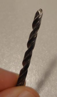
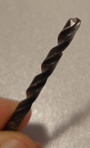
Stick some tape around the drill, so it won't damage the 'shaft' of the screw hole with its sides (we only need the tip of the drill).
Carefully place the drill in the center of the screw head, so it doesn't touch the side walls. Start drilling (counterclockwise of course) and keep the drill centered, away from the sides.
At first, the drill will start eating some of the screw head, that's fine. At some point it will get enough grip, so that it starts turning the screw. Once the screw gets halfway out, the drill is more likely to hit the side walls, so keep it centered!
Once the screws are out, the inside shows some wiring strips, a mains-powered PCB with 4 miniature relays and a CB3S module, and a separate PCB strip along the sockets, which holds the 4 LEDs:
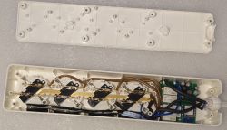
Note the grooves in the ball joint at the end of the cable. When reassembling the housing, this groove must point straight up and down, so they align with two notches in the housing halves.
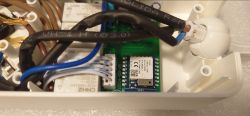
Make some temporary solder connections to the 1st, 2nd and last pin of the top row, and the last pin of the bottom row:
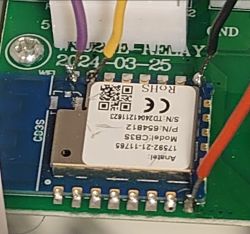
And connect them to a 3.3V TTL serial interface:
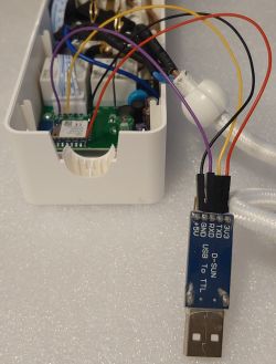
Colors don't matter, but in these pictures:
- black: Gnd
- red: +3.3V
- purple: Tx (smart plug) to Rx (PC)
- yellow: Tx (PC) to Rx (smart plug)
Some hints for flashing OBK:
- When the flashing software asks for a device reset, you can shortly pull and re-plug the red wire.
- This didn't work reliably for me. Instead, you can also momentarily connect pin 1 of the CB3S module (its reset input) to Gnd:

Device configuration:
As JSON:
Finally: when reassembling, use normal screws
I used 'tapping screws 2.9x16mm', but 2.9x13mm will probably also fit fine.


The device can be successfully used with OpenBeken, but requires some DIY skills to open the housing without damage.
BIG FAT WARNING: the electronics inside the power strip are directly connected to the 230V mains lines, without any isolation!
Keep the mains plug disconnected during the whole operation!
First, remove the 8 rubber feet (they pull out very easily):

Next, you'll find screws with a completely flat head surface. For the rest, they are normal self-tapping plastic screws:

So, how to get them out? As first attempt, I tried to drill them out. This ruined the plastic housing around the screws so badly, that it was almost impossible to reassemble the power strip again.
The second plan worked better: get an (old) metal drill bit (ca 4 mm diameter) and an electric grinding stone. Grind down the head of the drill bit, and create an 'opposite' cutting surface. In other words, let's create a left-turning drill.


Stick some tape around the drill, so it won't damage the 'shaft' of the screw hole with its sides (we only need the tip of the drill).
Carefully place the drill in the center of the screw head, so it doesn't touch the side walls. Start drilling (counterclockwise of course) and keep the drill centered, away from the sides.
At first, the drill will start eating some of the screw head, that's fine. At some point it will get enough grip, so that it starts turning the screw. Once the screw gets halfway out, the drill is more likely to hit the side walls, so keep it centered!
Once the screws are out, the inside shows some wiring strips, a mains-powered PCB with 4 miniature relays and a CB3S module, and a separate PCB strip along the sockets, which holds the 4 LEDs:

Note the grooves in the ball joint at the end of the cable. When reassembling the housing, this groove must point straight up and down, so they align with two notches in the housing halves.

Make some temporary solder connections to the 1st, 2nd and last pin of the top row, and the last pin of the bottom row:

And connect them to a 3.3V TTL serial interface:

Colors don't matter, but in these pictures:
- black: Gnd
- red: +3.3V
- purple: Tx (smart plug) to Rx (PC)
- yellow: Tx (PC) to Rx (smart plug)
Some hints for flashing OBK:
- When the flashing software asks for a device reset, you can shortly pull and re-plug the red wire.
- This didn't work reliably for me. Instead, you can also momentarily connect pin 1 of the CB3S module (its reset input) to Gnd:

Device configuration:
Code: Text
As JSON:
Code: JSON
Finally: when reassembling, use normal screws
I used 'tapping screws 2.9x16mm', but 2.9x13mm will probably also fit fine.
Cool? Ranking DIY


