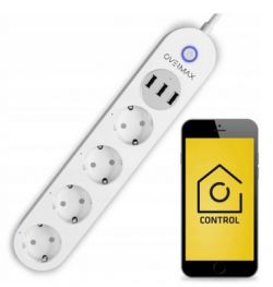
I invite you to a short presentation of the interior and to change the firmware of the strip/extension cord with four Schuko sockets and three USB ports with a total current capacity of only 2.1A. I will install Tasmota on the device in order to connect it with Home Assistant without the involvement of the manufacturer`s servers.
Purchase Overmax Flow Multi Control
The strip was purchased for PLN 125:
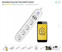
Below are screenshots of the offer:
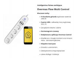
Declared 2.1A at 5V - we will check.
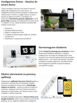
The rest of the description praises the manufacturer`s application, but we will still upload our own firmware:
Packaging with markings:
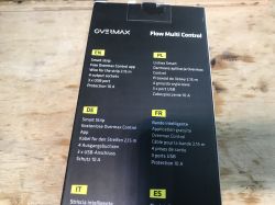

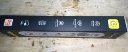
Unfortunately, I don`t see any specific model number here...
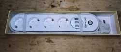
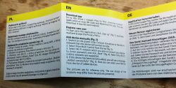
QR code for the full manual and short pairing instructions (PL and EN):

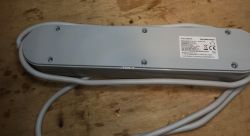
The bottom of the strip, the nameplate, this model is actually called Flow Multi Control:
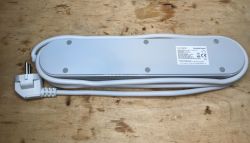
Overmax Flow Multi Control interior
The screws are hidden under the legs:
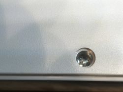
We unscrew it and look inside:
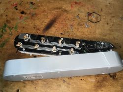
The wires hold the board, but it can be removed to some extent:
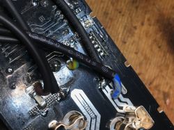
You can already see the WiFi module, IO0 indicates that there is ESP there:
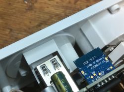
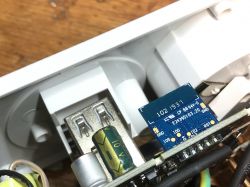
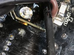
It is necessary to separate the upper part of the housing from the PCB unsoldering the thick pin from ground : :
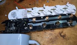
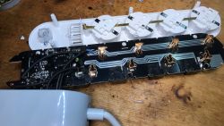
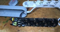
You can already see the relays and LEDs illuminating the sockets and the power supply section:
The relays are Y32F-SS-105HM:
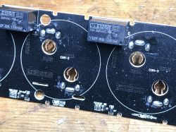
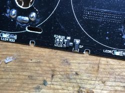
They are controlled by J3Y transistors:
Let`s look at the power supply section - it`s a regular flyback, without QC, it`s good that at least there is a fuse resistor, a varistor and a filter capacitor at the input:
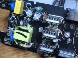
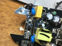
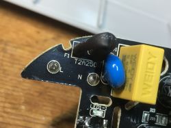
LittleI was surprised by the U3 circuit near the USB connectors, I thought it was something to do with charging negotiations, in cheaper products we simply have resistors that set the levels at D+ and D-:
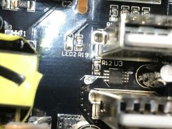
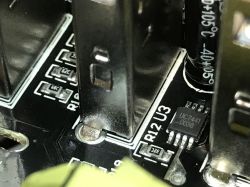
And yet UC7441 seems to be an overload protection, interesting:
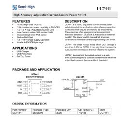
We look further:
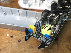
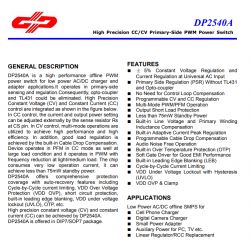
The power supply itself is based on DP2540A:
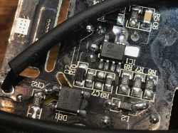
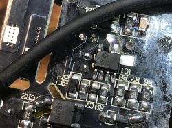
There is some information about it on the Internet:
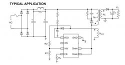
There is also an example diagram of such a converter, which in my opinion is the most typical circuit, which I have already discussed several times, so I will not comment on it further here:
Overmax Flow Multi Control firmware change
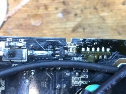
It is best to desolder TYWE2S, I recommend the flux + braid method:
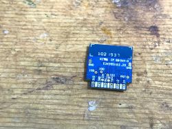
Then, according to the topics already described:
SmartLife switch - test, interior and programming of a WiFi light switch
I program via myself esptool.py , but there is also a solution in the browser:
How to easily install Tasmota - online installer tasmota.github.io/install via a web browser
Here`s my layout:
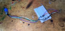
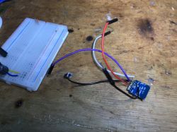
After a short test whether Tasmota creates an access point, TYWE2S returns to its place:
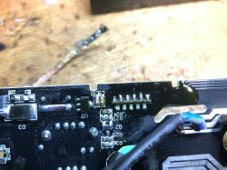
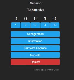
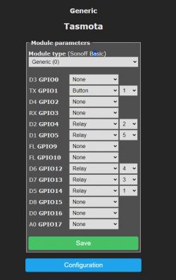
I quickly experimentally checked which GPIO was which relay:
Here is the final Tasmota configuration:
NOTE - when assembling, you need to solder the ground pin!
Current efficiency test
As a rule - looking at the interior, I think it will be OK, it`s not a total budget, but I don`t trust your word - will there be these 2.1A:
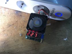
There is even more, 2.3A activates the protection, it`s ok.
Summary
A very interesting strip and I think I now know why the UC7441 is there - it`s because the WiFi module is also able to control the USB outputs, all together, but it`s still something. So basically we have as many as 5 channels here - 4 separate sockets and 1 common USB output. There is something to control.
This TYWE2S has almost all the free GPIO occupied, but fortunately it still works.
Flashing is hassle-free, you just need to remember that you need to desolder (and then solder in) the ground pin and similarly you also need to desolder (and then solder in) TYWE2S for the time of changing the firmware.
To sum up - in my opinion it`s ok, if you are looking for a strip for ESP (and not for BK), you can consider this product, although these schuko sockets are not something we would normally expect in our country...
Cool? Ranking DIY Helpful post? Buy me a coffee.


