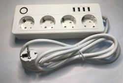
I'd like to invite you to a demonstration of the interior, construction and software change of yet another device offering remote control via Wi-Fi with a split between four 230 V sockets, a 5 V line (four USB ports together) and energy metering. The strip shown here is based on the BK7231N chip and normally works with the Tuya app, but here I will show how to upload our open batch ensuring compatibility with Home Assistant.
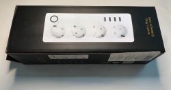
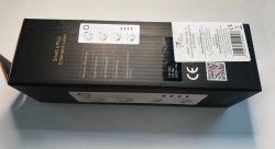
We bought the strip for around £120. It appears under the name SMART_STRIP_EU4_M, although this description may also fit similar products.
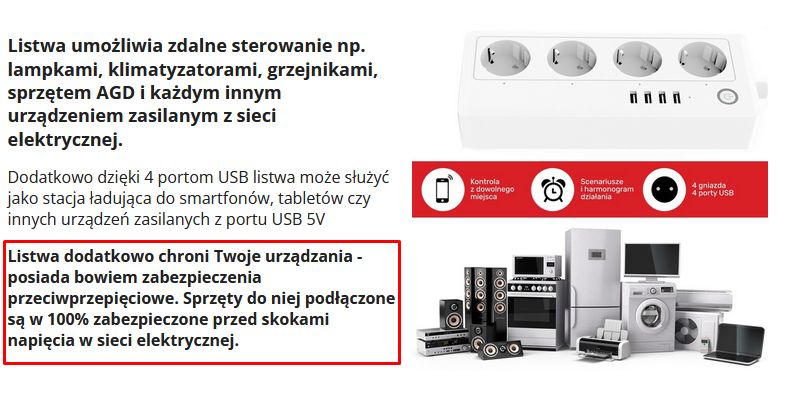
The product description is interesting in that it mentions anti-overvoltage (such as '100%' - I wonder how this was calculated).
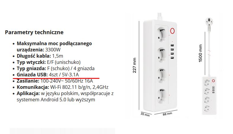
The USB power supply (5 V, up to 3.1 A) is also present. There is no QC support, USB will not attach higher voltage.
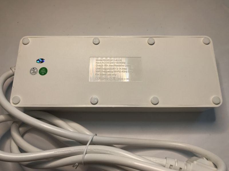
There is a different model on the bottom - RH-EU411-4U-W.
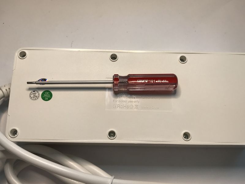
Inside of the product
It's time to take a look inside.
The interior is secured by slightly less typical screws requiring a triangular-tipped screwdriver.
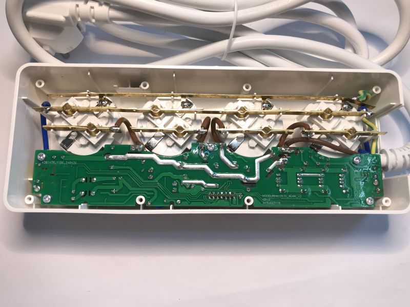
The design of the strip is not that bad. Even the earthing is connected - in the cheapest products only "pretend" happens. The thickness of the wires is not significantly underrated either.
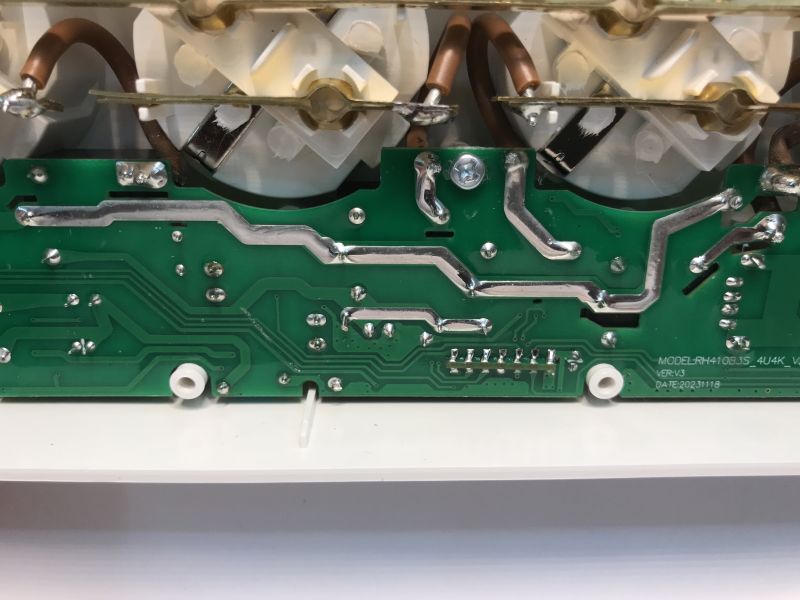
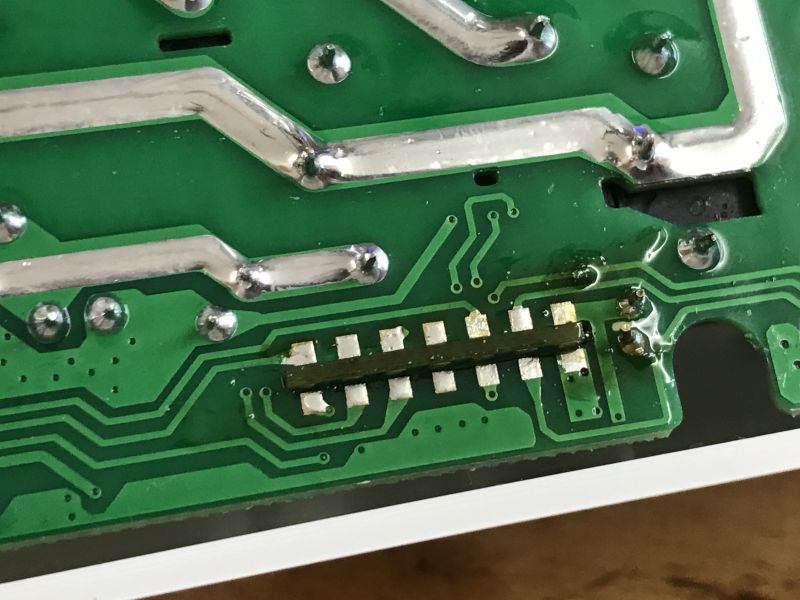
The PCB designation is RH410B3S_4U4K_V2, version V3. Date 20231118 Interestingly, you can also see the Wi-Fi module soldered into the board, but its pads do not resemble the standard CB2S/WB2S.
By removing the screws from the centre, the PCB can be lifted:
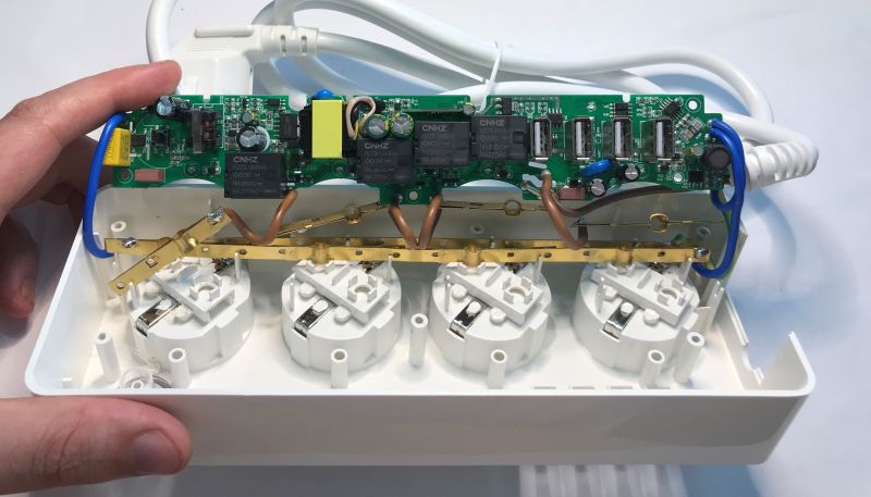
The whole thing doesn't look so bad. There are even filters against EMI emissions on the input. In addition, I can even see a varistor (surge protection) and, of course, relays - one per socket, CNHZ HZ73-1A5S-H at 5V.
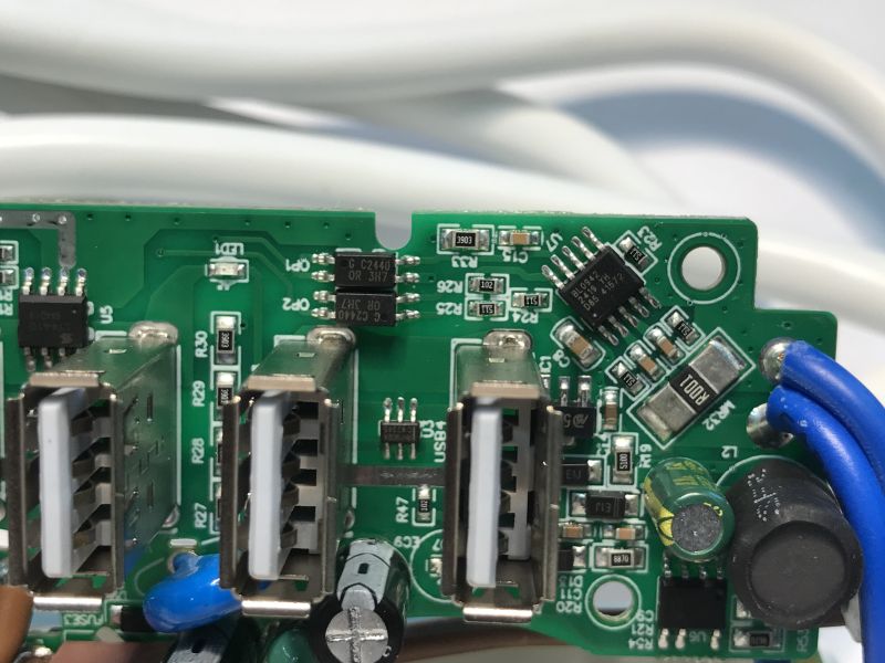
Here we see the BL0942 chip, it is used to measure voltage, current and power. It communicates with the Wi-Fi module via the UART. It looks like this UART is isolated - I can see two optocouplers there. Also visible next to it are the USB ports along with the U3 chip, which I'm betting is responsible for the power supply reporting to the connected device. Phones and mobile devices will not draw more than 500 mA without this. Sometimes you short-circuit the D+ and D- pins or set levels on them with resistors, but this is also not the best method and many devices will then not draw more than 1 A. A dedicated circuit is the best solution.
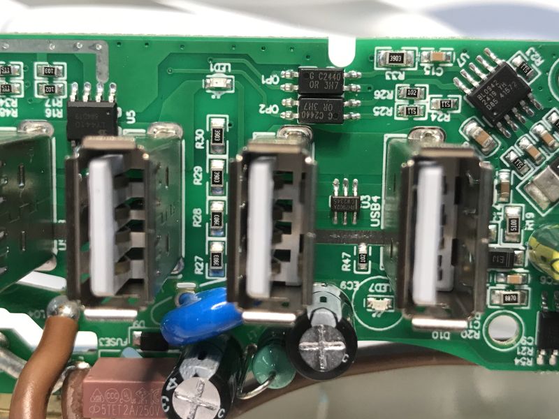
The designation of this circuit is RH7902A. It is designed for two USB ports.
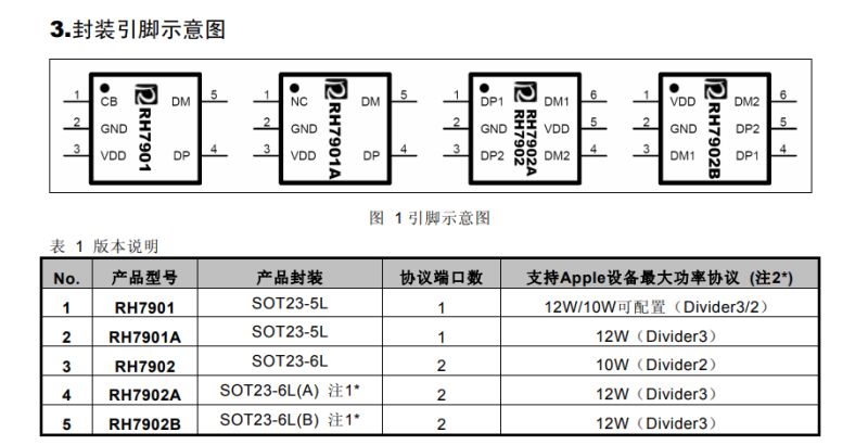
According to the catalogue note, this chip supports the following power supply notification protocols:
- Divider1 / Divider2 / Divider3 - charging protocols used in Apple devices
- D+ / D- = 1.2 V - Samsung compatible mode
- BC1.2 DCP - standard Battery Charging 1.2 protocol (Dedicated Charging Port)
- CTIS YD/T 1591-2009 - Chinese standard for charging mobile devices
Here you can see its second piece. There is an LDO AMS1117-3.3V next to it, too. And the L4410 (if I read it correctly), which is the MOSFET that the Wi-Fi module uses to switch on the 5 V line.
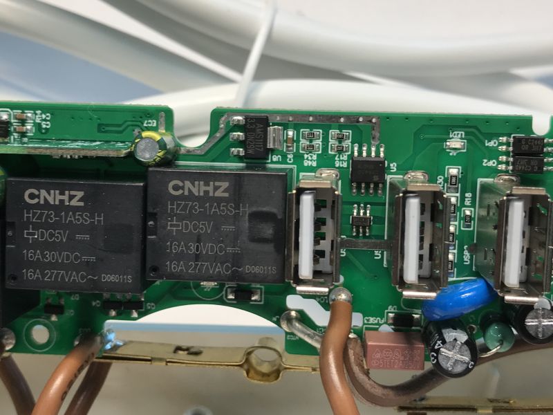
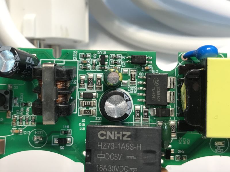
The relays are controlled by small transistors, here you can also see the secondary side of the inverter next to it, the distance between the "hot" and "cold" side seems to be ok:
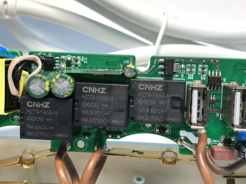
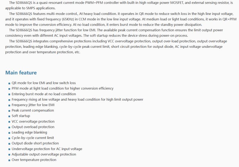
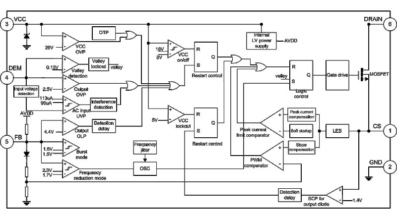
The inverter is in flyback topology and is based on an SD8666QS chip with an integrated MOSFET transistor.
Internal construction and leads:
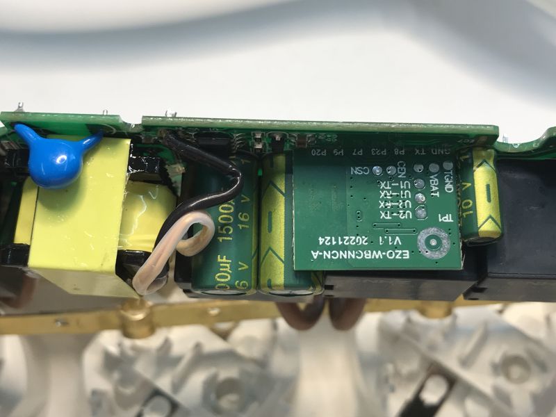
That leaves the Wi-Fi module - EZO-WBGNNCN-A V1.1 20221124 - I haven't seen this type yet:
ADVERTISEMENT
Firmware change
To upload our open-source firmware this serves our flasher , it too can detect the GPIO configurations of the device. You will need a USB to UART converter. You need to get to TX1/RX1 of the Beken chip, it is best to solder out the whole module to be sure. I use flux and braid for this. The flux makes it easier to melt the binder and the braid allows us to collect it and clean the pads.
The module is based on the BK7231N, the pads are signed, no need to guess.
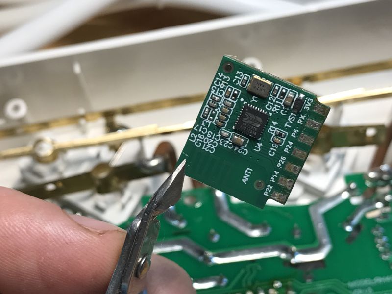
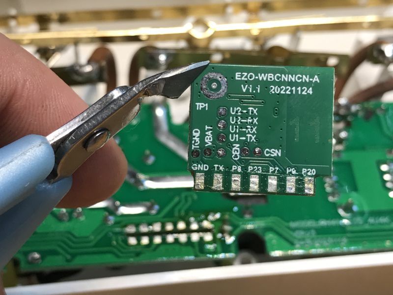
Before soldering, I will braze the pads with lead binder, such has a lower melting point:
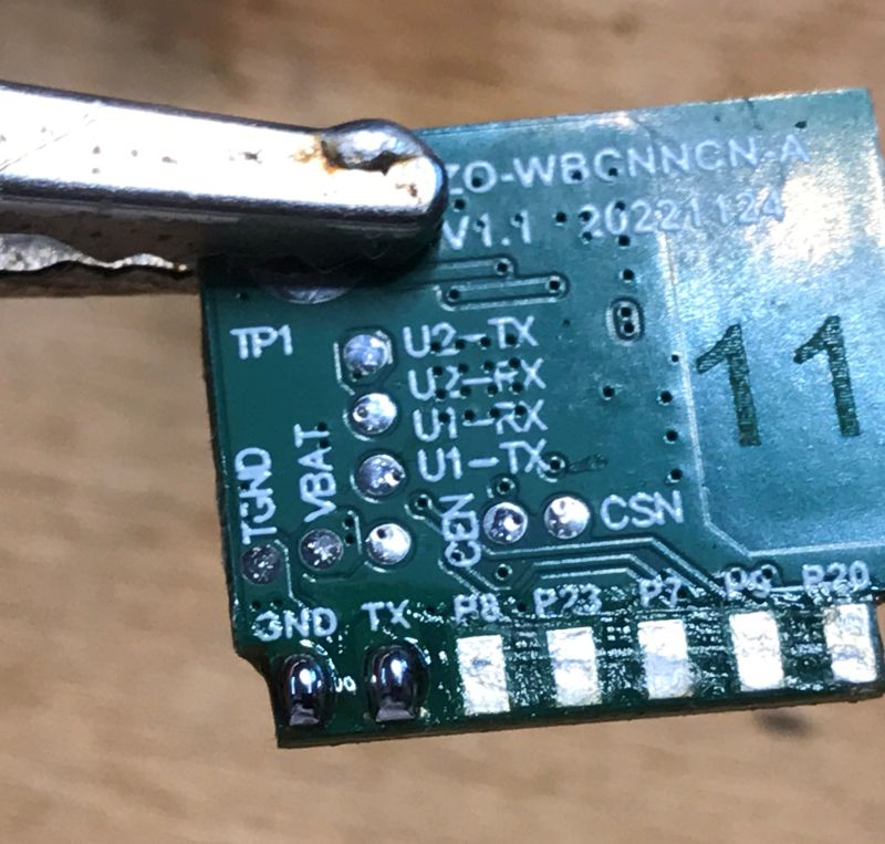
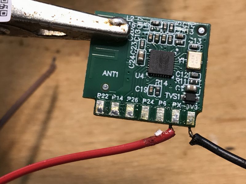
Then I solder the four wires - power supply and UART:
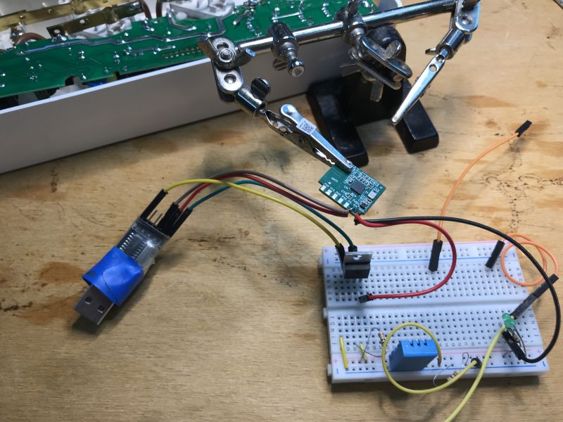
I additionally power the whole thing from an external 3.3 V LDO (the 3.3 V pin from the USB to UART converter does not have enough current capacity).
For programming I use our flasher , the flasher correctly detects the GPIO configuration:
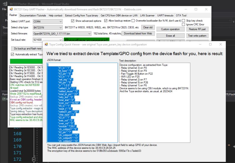
JSON Tuya:
Code: JSON
Verbal description:
Device seems to be using CBU module, which is BK7231N chip.
- Relay (channel 1) on P6
- Relay (channel 2) on P7
- Relay (channel 3) on P8
- Relay (channel 4) on P9
- Relay (channel 5) on P26
- WiFi LED on P20
- Pair/Toggle All Pin on P22
OBK template:
Code: JSON
Template import tutorial:
HA pairing tutorial:
Then we still calibrate and the strip already works 100% locally with Home Assistant.
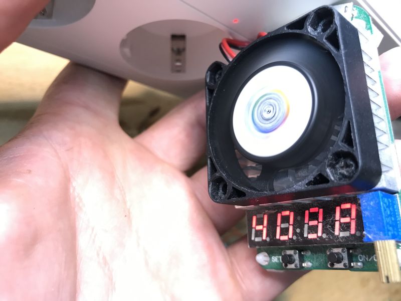
Current capacity test
I was able to draw up to 4 A from the strip, then the voltage drops significantly.
Summary
The offer description mentioned a current capacity of 3.1 A, and managed to achieve up to 4 A, so it's ok here, although there could also be QC supported.
What I don't like is the mention of surge protection ("surge protection"), with this I have my doubts - is this about the varistor in the power supply circuit? Or is it about the fact that if we remotely unplug the device, the surge will not damage it? Additionally, supposedly this protection is "100%", according to the description. Not good. In my opinion, this is misleading and this power strip is not anti-overvoltage.
However, the rest of the design of the strip seems to be quite good. There are filters against interference emissions in the power supply circuitry, the USB ports have dedicated circuitry to report themselves as a suitable power supply for phones, and the transformer itself also looks quite good.
Changing the firmware of this device turned out to be quite easy. It was enough to solder out the Wi-Fi module. Each of the sockets is controlled separately, this is realised based on relays, while the USB ports are switched together based on a MOSFET transistor.
The strip also offers voltage, current and power measurement realised on the BL0942, which is connected to the Wi-Fi module via UART. After changing the batch, calibration is required, as in Tasmot, VoltageSet/PowerSet/CurrentSet commands.
I think that as a 'smart' gadget this product can be bought, while it is not suitable for surge protection of equipment.
Do you see applications for this type of strip?
Cool? Ranking DIY Helpful post? Buy me a coffee.


