Arduino Nano Interactive Piano: 6 Obstacle Avoidance Modules with DF MP3 Module Setup
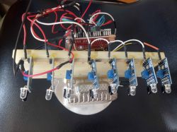
Today, I would like to introduce an interactive Arduino music project. Using six obstacle avoidance modules and DF’s MP3 module, we will build a musical piano (originally, I had eight obstacle avoidance modules, but during assembly, I found that two were incompatible and lacked indicator lights. Since replacing them in time was not feasible, I wrote code to adapt the system for six modules. The central controller uses an Arduino Nano paired with a Nano expansion board. The threshold (threshold) of the obstacle avoidance modules must be adjusted using the module's built-in regulator. In this circuit design, one can also draw parallels to the avalanche diode (though not directly used in this project's hardware, it serves functions such as circuit protection and high-speed switching in complex electronic circuits, sharing similar underlying principles with our project's pursuit of circuit stability and signal accuracy).This concept could be explored further if the project is expanded in the future. The coordinated operation of various modules in the project is akin to understanding the structure and collaboration of DC motor components, where different components work together in an orderly manner to achieve the overall function.
Step 1: Operation Process
Connect the 6 obstacle avoidance modules: GND and VCC are connected to the breadboard, and the signal lines are connected to the corresponding pins on the Nano.
Write and burn the code.
Power on and test.
Adjust the trimmer (fine-tuning device): Only one green LED should be lit on the module. If both are lit simultaneously, the MP3 module will output abnormal audio.
Step 2: Hardware Setup
Name Quantity
DFRobot nano 1
Obstacle avoidance module 6
Breadboard 1
nano expansion board 1
5V Power Bank 1
Step 3: Understand the key hardware parameters
Sound effect file download
1. This module comes with built-in sound effects. If you need to add or replace sound effects, you can use a micro USB cable to connect to a computer for updates and downloads;
2. The method for updating sound effect files is the same as using a USB drive.
3. The device supports MP3 and MAV format audio files;
4. Files must be stored in the "2H" folder. It is recommended to use numerical names, e.g., 01.mp3, 02.mp3. Alternatively, two letters or a single Chinese character can be used for naming.
Wiring diagram
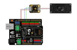
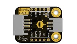
The Gravity UART module features a variety of pin functions. The TX (T) and RX (R) pins are used for serial communication; the power ground, power positive (3.3V - 5V, including VCC) form the power supply system to ensure stable power supply to the module; The BUSY pin serves as a busy signal pin, presenting a high voltage level during playback and a low voltage level in other states; the SP+ and SP- pins are connected to the speaker and are responsible for audio output; the DACL and DACR pins correspond to the left and right channels of the DAC audio output, respectively; the ONE pin is a single-wire serial port control pin that can be used to achieve specific control functions; The micro USB pin serves as an interface for updating audio files. It connects to a computer via USB, with a storage method similar to a USB drive, facilitating the updating of audio files. The pins work together to enable the module to function in scenarios such as serial communication and audio processing. By dividing tasks among different pins, the module achieves data transmission, power supply, audio output control, and file update functions, providing flexible and practical hardware support for related applications.
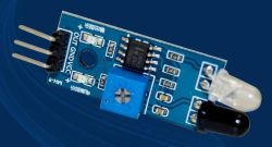
When the module detects an obstacle signal in front, the green indicator light on the circuit board illuminates, and the 0UT port continuously outputs a low-level signal. The module has a detection range of 2–30 cm and a detection angle of 35°. The detection range can be adjusted via a potentiometer: turning the potentiometer clockwise increases the detection range, while turning it counterclockwise decreases the detection range.
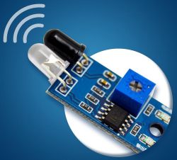
This is an active infrared reflection detection sensor with strong adaptability to ambient light conditions. It operates using a pair of infrared emitter and receiver tubes. The emitter tube emits infrared light at a specific frequency. When the infrared light encounters an obstacle, it is reflected and received by the receiver tube. After processing by the comparator circuit, the green indicator light illuminates, and the signal output interface simultaneously outputs a low-level digital signal. The detection distance is related to the target's reflectivity and shape. Black targets and small objects have a shorter detection distance, while white targets and large objects have a longer detection distance. The effective detection range is 2–30 cm, adjustable via the potentiometer knob. The operating voltage is 3.3V–5V, and it can output a digital signal to assist external devices in determining the status of obstacles.
Step 4: Provide some hardware images for a visual reference

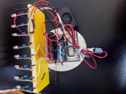
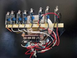
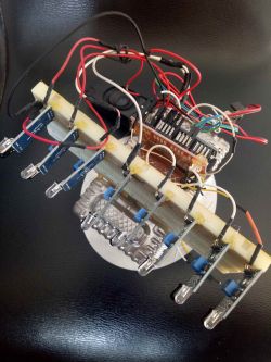
Step 5: Introduction to the key code
Code: C / C++
Code Function Description: Use the SoftwareSerial library to create a software serial port for communication with the MP3 module; define 6 obstacle avoidance module pins and write functions for playback and volume control; the setup function initializes the pins as input mode, configures the serial port, and sets the initial volume; the loop function continuously monitors the obstacle avoidance module signals, and a low-level signal triggers the corresponding audio playback.
Step 6: Wiring diagram
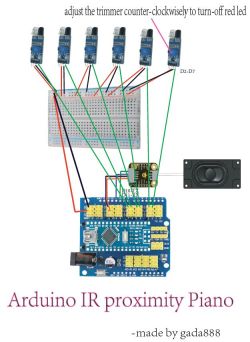
Step 7: Summary
This project utilizes hardware such as Arduino Nano to create an interactive musical piano using obstacle avoidance modules and MP3 modules, achieving basic obstacle detection and audio playback functionality. In practice, it was discovered that there is mutual interference between modules. Suppose the head of the obstacle avoidance module is wrapped (e.g., with a material that does not interfere with infrared signals to create a simple shield). In that case, the probability of interference can be reduced, as wrapping reduces infrared signal scattering and false triggers. Further improvements can be made in the following areas: first, optimize the code logic to handle complex scenarios where multiple obstacle avoidance modules trigger simultaneously, enabling more diverse audio playback (e.g., different modules triggering different melodies); second, expand hardware functionality by incorporating avalanche diodes, which are used in circuit protection and signal optimization, to enhance the circuit's interference resistance and ensure more stable signal transmission; Third, compare the system coordination modes of DC motor components and improve the physical fixation and signal coordination among the modules in this project. For example, provide a unified shielding cover for the modules to fix their positions and reduce interference, making the overall system more reliable and functional.


Comments
Hello, If you would still use laser diodes with optics and a bit of smoke to scatter the light, we would have a laser harp by J.M. Jarre :) . Admittedly, this is still a long way from an instrument,... [Read more]