logo elektroda
logo elektroda
X
logo elektroda

125kHz RFID reader with integrated antenna, Attiny13A

mjc 25589 18
ADVERTISEMENT
Treść została przetłumaczona polish » english Zobacz oryginalną wersję tematu
  • 125kHz RFID reader with integrated antenna, Attiny13A


    Hello.
    I have been interested in RFID technology for a long time and today I would like to present the development of my old design, namely an RFID card reader with an integrated antenna on a PCB.

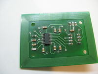
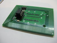
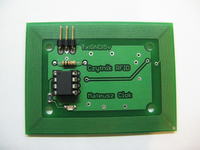
    Due to the complicated structure of the antenna (small distances between the paths), the board was ordered from an external company. The heart of the project is the Attiny13A microcontroller and the EM4095 transreceiver. I used the processor in a DIP housing, because I do not have an adapter for SMD programming. Except for one resistor, everything else is in the SMD 1206. The circuit is unusual because virtually all other projects are based on large processors, eg Atmega8, Atmega32, PIC16Fxx etc., but I couldn't find something on such a small circuit.

    The reader reads cards as standard UNIQUE at 125kHz . Cards are encoded with a 64-bit unique serial number.
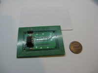
    As I mentioned, the board was commissioned to an external company - XXXXX. I am very pleased with the performance - no short circuits, despite the small distance between the tracks. High-quality tin-plating, metallization and solder mask - does not come off when heated with a soldering iron. I think that the most interesting element of the board is the antenna - it has a range of about 8 cm with the Unique card. The board has a 3x godpin strip - Tx respectively - data transmission in the TTL, GND, VCC standard (5V, also checked 3.3V - works, but the range is visibly smaller).

    On the board, in addition to the processor and strip mentioned above, there is an LED signaling the card reading and the standard application of the EM4095 chip.

    Firmware - microcontroller software
    The software has been significantly changed compared to the first version published in the topic Link .

    * increased transmission speed to 19200bps

    * data is not sent as ASCII characters but as data bits. I gave up the data as ASCII code due to the simpler implementation of the algorithm in the receiving programs, either on the PC or on the AVR. Data sent this way may not be readable in some programs (eg PuTTY or hyperterminal), so I recommend Bray ++ Terminal. After putting the terminal in HEX mode, we get nice data.

    * added XOR checksum. The biggest disadvantage of the previous version was the lack of a checksum. The XOR checksum is calculated according to the algorithm: (1-byte of card code data) XOR (2-byte of data card codes) XOR (3-byte of data card codes) XOR (4-byte of data card codes) XOR (5-byte of data codes cards),

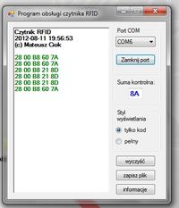
    e.g. we have a card specified with numbers in hexadecimal notation: 28 00 B8 60 7A then the XOR checksum looks as follows:
    (28) xor (00) xor (B8) xor (60) xor (7A) = (28) ^ (00) ^ (B8) ^ (60) ^ (7A) = 8A


    The reader sends 9 bytes of data:
    1. # 7Eh - transmission start symbol
    2.1-byte card code data (MSB)
    3.2-byte card code data
    4. 3-byte card code data
    5. 4-byte card code data
    6.5-byte card code data (LSB)
    7. # 5Eh - symbol of transm. check totals
    8. Checksum - XOR checksum
    9. # 7Ch - symbol of end of transmission

    If the card is kept in the reader field continuously, such a frame is sent every 700ms. The reader informs that the card has been read by lighting the LED for 350ms.

    Due to the lack of a hardware USART interface in the microcontroller, it was necessary to use a software implementation of the UART. It is a constantly developed version and I hope that it is free from bugs and flaws. At this point, I have a question for more experienced users: how do you test this type of solution?

    The program, during its work cycle, after the initial reading of the card number, decodes it (Manchester encoding) and checks the parity, this prevents sending an incorrectly received code to the receiving device (e.g. some interference, etc.).

    Of course, the program was written in C (Avr Studio 4 + WinAVR-20100110) and partly in Assembler - I cannot imagine implementing this problem in the BASCOM environment for such a small processor as Attiny13. BASCOM offers RFID support through a few simple commands, but it is a terribly suboptimal solution, it takes up an awful lot of memory and is suitable for Atmega rather than Attiny.

    The program takes 788 bytes.

    Gross costs

    Board: PLN 27 / piece (prototype)
    EM4095: PLN 10
    Attiny 13A: PLN 4.5
    General cargo: less than PLN 1

    I wrote a PC software for the reader in C # 2010. I chose the platform mainly because of the license for the entire Visual Studio package, but also the built-in, very good serial port control. The program receives data from a designated serial port, analyzes them in terms of header and checksum compliance - if everything is correct - the data goes to the user. In a similar style, I wrote uC programs in the two most popular C languages (avr-gcc) and BASCOM-BASIC.

    Due to the inability to make a tile with home methods, I do not publish the pattern of the paths.

    When selecting capacitors for EM4095, using the Excel file provided by the manufacturer may be inconvenient, so I wrote a simple program EM4095 Dsigner Tool presenting the data in an accessible form.

    Plans for the future:

    In the future, I plan to modify the Attiny PCB in SMD and add a Watch-Dog to the program.

    When soldering, unfortunately I touched one via with the tip, which made it an unsightly "tuber". I am also not satisfied with the angular goldpin strip, but it was the only one I had.

    To sum up:

    I am very pleased with the design. It does the job and I hope it looks nice.
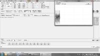
    In the attachment I am adding a diagram, a program for receiving data (you can see what the interface looks like), the EM4095 Designer Tool program, about which I wrote earlier, and catalog notes for the EM4095 system.
    I do not include the HEX file this time.
    I used materials widely available on the Internet to develop the project.

    Moderated By androot:

    Removed the name of the tile company - surreptitious advertising


    A few pictures:
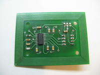
    125kHz RFID reader with integrated antenna, Attiny13A 125kHz RFID reader with integrated antenna, Attiny13A 125kHz RFID reader with integrated antenna, Attiny13A 125kHz RFID reader with integrated antenna, Attiny13A
    125kHz RFID reader with integrated antenna, Attiny13A 125kHz RFID reader with integrated antenna, Attiny13A

    Cool? Ranking DIY
    About Author
    mjc
    Level 14  
    Offline 
    mjc wrote 165 posts with rating 107. Live in city Siedlce. Been with us since 2012 year.
  • ADVERTISEMENT
  • #2 11199218
    blue_17
    Level 32  
    What did you do PCB and how did you count the antenna :?:

    In eagle :?: maybe you used some script :?:

    Regards
  • ADVERTISEMENT
  • #3 11199280
    mjc
    Level 14  
    The CAD software does not matter - you have to create paths "on the spot" anyway. You can count, but it is time-consuming, for measurement you should use an oscilloscope - RLC system at 125kHz, you can use simulation software.

    As for the calculations, they are interesting, I would even say very good Microchip articles, but at the moment I cannot find, probably AN710
  • #4 11199322
    sedr
    Level 17  
    I recommend Micorwave Office for counting and guiding antennas.
  • #5 11199367
    vayo
    Level 14  
    Hello,
    cool design. I also became interested in RFID and the EM4095 chip about two years ago, but I didn't play with the hardware, because a lot of it is available online. I bought a ready reader with this chip for ATmega8 and wrote my batch for uC and software for PC. I wrote the batch myself, because I bought a reader and made it a "recorder". You can see how it works in the videos below


    greetings

    vayo
  • ADVERTISEMENT
  • #6 11199391
    piotrva
    VIP Meritorious for electroda.pl
    Such question, what cards does the colleague use to enter his ID? Where did a colleague buy such? I wanted to get one too, but in Poland it is hard ...
  • #7 11199398
    blue_17
    Level 32  
    m4tc10k wrote:
    The CAD software does not matter - you have to create paths "on the spot" anyway. You can count, but it is time-consuming


    I think it does :) because in a good EDA system there are tools that allow you to generate such antennas

    Regards
  • ADVERTISEMENT
  • #8 11199416
    vayo
    Level 14  
    piotrva wrote:
    Such a question, what cards does the colleague use to enter his ID? Where did a colleague buy such? I wanted to get one too, but in Poland it is hard ...


    I used Q5 and bought it about two years ago here Link
  • #9 11199788
    Urgon
    Level 38  
    AVE ...

    I really like the project itself. But since you can read cards, you can also burn and emulate them. Maybe you could modify this chip to emulate the read card?
    And about RFID projects, this is this is the smallest RFID emulator on a microcontroller ...
  • #10 11200075
    Anonymous
    Anonymous  
  • #11 11200367
    mjc
    Level 14  
    As for emulation, I am afraid that there is not enough processor memory for it, it would be necessary to switch to some atmega.

    R-MIK thanks for your attention, I will definitely use it.
  • #12 11200960
    RomanFilipecki
    Level 18  
    Everything is fine, but what are you planning next for this project?
    There are readers available, at least from two Polish producers, maybe there is a niche on the market?
  • #13 11201030
    mjc
    Level 14  
    Hello

    I know that there is a niche on the market, but unfortunately the price of my solution is not the lowest and I cannot think about competition.
  • #14 11201398
    Olo999
    Level 21  
    Could you give the "internal" dimensions of the antenna (length, width), width of the tracks and the distance between them?
  • #15 11223197
    Wojtek001
    Level 15  
    Can you count on a program listing?
    I would like to write this type of program in BASCOM but without using these ready-made procedures, therefore the listing in C would be useful for me.
  • #16 11224805
    mjc
    Level 14  
    Wojtek001 wrote:
    Can you count on a program listing?
    I would like to write this type of program in BASCOM but without using these ready-made procedures, therefore the listing in C would be useful for me.


    BASCOM and C it is a big difference.

    I will not share the source code.
  • #17 11278747
    r06ert
    Level 25  
    Hello,

    How does the EM4095 chip work? Is the device sensitive to changes in temperature and humidity? What is the range? And the most important question: If the tag will be in the reader's reach all the time, will it always be there always read what these 700ms? But is it not and it is caused by transmission (reading) errors?

    Regards

    Robert
  • #18 11279616
    mjc
    Level 14  
    r06ert wrote:

    How does the EM4095 chip work?

    I am very happy with it and the layout itself is the basis of many commercial products.
    r06ert wrote:

    Is the device sensitive to changes in temperature and humidity?

    Temperature and humidity changes are a widely understood phenomenon. It is logical that the circuit will not work at a temperature of 100 degrees etc. As for the usual fluctuations of +/- 10 resp. room, I did not notice any adverse effects
    r06ert wrote:

    What is the range?

    about 8cm, but it depends on the proximity of large metal objects and the type of transponder, with a key ring the range is much smaller.

    r06ert wrote:

    if the tag will be within the reader's range all the time, will it always read it every 700ms? But is it not and it is caused by transmission (reading) errors?

    by definition, always but sometimes something will disturb the reading (if it is, for example, the twentieth or thirtieth if you are constantly holding it) and you have to literally take the card for a moment. There are definitely fewer such cases if you hold the card closer and in your hand and not put it on the reader's plate. The program of the controller and the PC is written in such a way as not to show the wrongly read or sent data.
    ---
    greetings
  • #19 15959329
    Julio R
    Level 1  
    forum friends good.
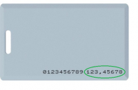
    my name is julio rojas i am in bogota colombia i want to ask there is a special favor for the EM4095 RFID reader and ATtiny13 the reader works fine but i want to know if someone can help me make a program modification for the TX serial port shows a code card like this in a circle green image cards attached thank you very much and look forward to your prompt reply.

    this is my mail, if anyone can help me: julroj07(_at_)gmail.com

Topic summary

The discussion revolves around the development of a 125kHz RFID card reader utilizing an Attiny13A microcontroller and an EM4095 transceiver, featuring an integrated antenna on a PCB. The author highlights the complexity of designing the antenna, which required external PCB fabrication due to tight spacing between paths. Various participants inquire about the design process, antenna calculations, and software programming. Recommendations for CAD software, such as Microwave Office, are provided for antenna design. The author shares insights on the reader's performance, including its range and sensitivity to environmental factors. Additionally, there are discussions about potential modifications for card emulation and the availability of RFID cards in Poland.
Summary generated by the language model.
ADVERTISEMENT