logo elektroda
logo elektroda
X
logo elektroda

GSM SIM800L modules from Allegro - antenna line quality and project application

Atlantis86 2811 16
ADVERTISEMENT
Treść została przetłumaczona polish » english Zobacz oryginalną wersję tematu
  • #1 16808792
    Atlantis86
    Level 19  
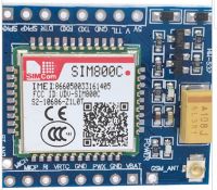
    Cheap SIM800L GSM module boards have been available on Allegro for a while now. Usually mounted on a red laminate, they are characterised by their small size and, as far as I can see, are quite popular among Arduino users. Or at least this is indicated by the not inconsiderable number of tutorials on the Web. Image attached.
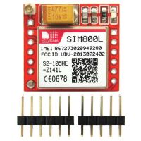
    GSM SIM800L modules from Allegro - antenna line quality and project application .

    I am currently working on the design of a certain device that will need GSM connectivity. Mainly receiving SMS and occasionally GRPS - the latter for, among other things, time synchronisation with NTP. Using such a module would simplify my board design quite a bit.
    However, after looking at the pictures, the first doubts arose. Namely, the antenna line does not look like it was designed according to the rules of art. The path winds next to another solder field, and the adjacent ground fields are in quite close proximity and are not connected to the general ground on the other side of the board. It does not resemble, for example, a microstrip line in any way....

    Does the module work properly and perform well despite this? I ask because I have come across one piece of information about GSM transmission interfering with its own UART communication. At the same time, from what I can see the modules are quite popular.

    Someone may have dealt with them and can share an opinion?
  • ADVERTISEMENT
  • #2 16808826
    czareqpl
    Level 33  
    And searching for topics on the electrode tried?
    There are several topics where people have used these modules (including me).

    They perform quite well. You just have to take care of a good power supply.
  • #3 16808922
    czasnagli
    Level 17  
    Atlantis86 wrote:
    Does the module work properly and perform well despite this?


    The sim800l works fine, but for about $4 on aliexpress you can buy a sim800c. See how many useful pins are brought out in the sim800c. It also has bluetooth.

    GSM SIM800L modules from Allegro - antenna line quality and project application .
  • ADVERTISEMENT
  • #4 16808947
    Anonymous
    Anonymous  
  • #5 16809117
    simw
    Level 27  
    niveasoft wrote:
    .
    This diagnostic message from the SIM comes with a 100% good 4.0V supply so I submit this for your consideration.

    It is worthwhile in your software to listen to what the module is writing.


    From what I've read in the literature, a very common cause of problems with gsm modules is bad PCB and power supply design, as the thread author also wrote about. The module takes relatively a lot of current in the operating mode and therefore, in a nutshell, it is easy to "generate pins on the power supply". So much for the literature. I haven't run these modules myself yet, so I can't confirm this.

    Colleague niveasoft seems to be suggesting that the modules themselves are tref, since he writes about "100% good 4.0V power supply", at least that's how I perceive it myself, but I could be wrong.
    Please elaborate on this thought. The PCB for this module is a handmade one or is it some kind of "spider"? Was the power supply checked on an oscilloscope?
    I am very curious...
  • #6 16809211
    czareqpl
    Level 33  
    I'll add a piece of my solution:

    Diagram excerpt:
    GSM SIM800L modules from Allegro - antenna line quality and project application .

    A coil in the ground and power supply cuts off buzzing during data/audio connections. In this way I have ensured silent operation for the audio path.

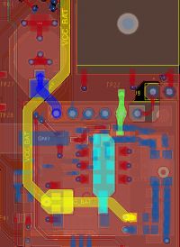
    PCB fragment:
    GSM SIM800L modules from Allegro - antenna line quality and project application .

    Greetings and best wishes for success.
  • #7 16809846
    Anonymous
    Anonymous  
  • #8 16810066
    czareqpl
    Level 33  
    R-MIK wrote:
    This is probably not the best idea.


    Not the best but effective.
  • ADVERTISEMENT
  • #9 16810095
    Anonymous
    Anonymous  
  • #10 16810178
    Anonymous
    Anonymous  
  • #11 16810270
    czareqpl
    Level 33  
    R-MIK wrote:
    And maybe the problem is in the PCB (ground) design
    .
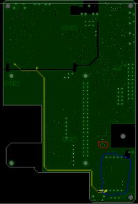
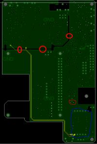
    Some advice on how to route the ground plane would be useful in that case:
    In blue I have marked the position of the SIM800L module.
    In red I have marked the connection point of the coil to ground.
    In yellow colour I have marked the paths with the audio signal, which is sensitive to hum from the GSM module.
    In the upper left is the audio section.


    GSM SIM800L modules from Allegro - antenna line quality and project application .

    Any advice from a colleague?
  • ADVERTISEMENT
  • #12 16810305
    krzbor
    Level 28  
    I have this module, it works very well. However, I bought it with a PCB antenna plugged into the socket. What surprised me was the audio working well - I thought with that much power in the antenna the unshielded cables to the microphone and speaker would be a problem. Just one piece of advice - I did tests on a contact board and it wouldn't work - it turned out that the contacts on this board have too much resistance (the Chinese made them out of steel, I think). This circuit really draws a lot of current. If anyone is having trouble with the stability of this circuit, start by checking the power supply (its efficiency).
  • #13 16810456
    simw
    Level 27  
    The maximum current for such modules can be up to 2A in about 0.5ms. The power supply must be designed so that the supply voltage does not drop by more than 300mV - data for the SIM800f module (if I remember the model correctly). It turns out that the problem may be the thermopads themselves at the pins, and other thin paths on which, at 2A, too much voltage drop may occur - by the way, a similar effect is observed with poor quality usb cables supplying power to mobiles or even RPIs.
    With errors in the above, even connecting to high-efficiency sources such as batteries or laboratory power supplies will have no positive effect.
  • #14 16817437
    Atlantis86
    Level 19  
    Among other reasons, this is why I do not use thermal pads on my boards.
    And of course I intend to put at least two suitably large tantalum capacitors at the module power pin.

    BTW I have read that it is condemned to put small filter capacitors on the RX and TX lines of the module. Is it advisable to use similar filtering also on the second UART interface (debug)? What about the other communication interfaces (SPI, USB, etc.)?
  • #15 16817490
    Anonymous
    Anonymous  
  • #16 16818048
    Szaflik
    Level 20  
    Has at least the "minimum" filter on the audio lines recommended by the manufacturer been implemented on the PCB ? (Figure 30 of the hardware design: "Speaker reference circuit") ? In the picture of the PCB it looks as if the audio paths are coming directly out of the module.
  • #17 18479046
    neo_84
    Level 15  
    As long as you don't need an audio track, everything looks fairly easy. Unfortunately I managed to make one board on which the microphone worked really well . Recently I received new boards (different shape pcb) ready beautiful non-thermal transfer but unfortunately failure :( the problem is probably with the antenna as some colleague wrote does not radiate power. If I cut my hand between the antenna and sima covers as if the plate interference disappears and the current decreases

Topic summary

The discussion focuses on the use of cheap SIM800L GSM modules from Allegro, popular among Arduino users for GSM connectivity including SMS reception and occasional GPRS for NTP time synchronization. Concerns were raised about the antenna line design on these modules, noting non-ideal PCB layout with winding antenna traces near solder fields and isolated ground areas not connected to the main ground plane, potentially affecting RF performance. Several contributors emphasized the critical importance of a stable, low-noise power supply capable of delivering peak currents up to 2A in short bursts to avoid voltage drops and module resets. The SIM800L module can self-manage network login and power states but is sensitive to antenna quality and power supply integrity. Alternative modules like the SIM800C, which offers more pins and Bluetooth, were suggested. Proper PCB design practices were discussed, including grounding strategies, filtering on audio lines, and avoiding capacitors on UART and SPI lines to prevent data transmission errors. The use of coils in ground lines was debated, with caution advised due to potential ground potential differences. Practical advice included using large tantalum capacitors near power pins, ensuring minimal resistance in power contacts, and following manufacturer recommendations for audio filtering circuits. Some users reported issues with antenna radiation and interference, which could be mitigated by physical adjustments. Overall, the thread highlights the challenges of integrating low-cost GSM modules into custom boards, stressing careful attention to antenna layout, power supply design, and signal integrity for reliable operation.
Summary generated by the language model.
ADVERTISEMENT