Currently, in the era of simple and inexpensive GSM modules and Arduino modules, it is very easy to construct an SMS-controlled relay. In the project below, the author used the SIM800L module to receive SMS messages. The whole system is controlled by the Arduino Nano V3 module. The system is equipped with one relay, which is controlled by SMS, which allows you to remotely turn on and off current in a circuit with the help of one SMS.
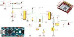
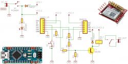
Let's look at the schematic diagram of the system first - these are just a handful of discrete elements, next to the two modules mentioned above:
The system is powered by stabilized voltage of 5 V from a 1 A power supply. This voltage supplies the Arduino board with a microcontroller, and the GSM modem is powered by 4.3 V. Most SIM800L modules available on the market should work without a problem with 3.7 V, however, the author found that his modem works with voltages below 4 V on average, hence the supply voltage of 4.3 V.
The program code on Arduino is very simple. The modem does not require any dedicated libraries, and communication with it takes place via a simple serial interface. RX and TX pins are configured as a software serial port through which Arduino communicates with the SIM800L module. This is deliberate because it allows you to eavesdrop on this transmission for debugging code.
After making sure that all the elements are connected correctly and uploading the following program to the Arduino module, you can start the device. First, we must insert the SIM card into the modem. After starting in a few seconds the card should register in the network - the modem will signal it by blinking every few (2..3) seconds with the LED. At this point, we can press the reset button to fully boot the system.
Now you only need to send an SMS to the SIM card number. After sending the SMS saying "ON" the relay will turn on and the SMS saying "OFF" will turn the relay off. The layout does not distinguish between uppercase and lowercase letters. The relay can be connected to any device that we want to control. Just remember not to exceed the maximum permissible current and voltage of the relay contacts.
The program code is very simple. That's him:
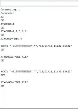
And this is what communication on the serial port looks like through a monitor connected to it during system operation.
Finally, some important tips:
* The SIM card must be inserted into the slot so that it protrudes from the cut end, as shown in the picture.
* The SIM800L module needs a supply voltage from 3.4 V to 4.4 V and a current from 1 to 2 A. The module has neither an integrated voltage stabilizer nor a signal level translation system - we have to build these elements ourselves.
* The power supply must have adequate current capacity. If the voltage drops excessively, the modem may shut down unexpectedly or reset during operation.
* If something does not work in the system shown, it is a good idea to perform a hard system reset.
* The program code, however working, may require some corrections etc., so it is good to follow it step by step and possibly make your own modifications. The author (link below) will gladly know if he made any mistakes in the program.
Source: http://www.electroschematics.com/13641/sim800l-one-channel-sms-relay/
Let's look at the schematic diagram of the system first - these are just a handful of discrete elements, next to the two modules mentioned above:
The system is powered by stabilized voltage of 5 V from a 1 A power supply. This voltage supplies the Arduino board with a microcontroller, and the GSM modem is powered by 4.3 V. Most SIM800L modules available on the market should work without a problem with 3.7 V, however, the author found that his modem works with voltages below 4 V on average, hence the supply voltage of 4.3 V.
The program code on Arduino is very simple. The modem does not require any dedicated libraries, and communication with it takes place via a simple serial interface. RX and TX pins are configured as a software serial port through which Arduino communicates with the SIM800L module. This is deliberate because it allows you to eavesdrop on this transmission for debugging code.
After making sure that all the elements are connected correctly and uploading the following program to the Arduino module, you can start the device. First, we must insert the SIM card into the modem. After starting in a few seconds the card should register in the network - the modem will signal it by blinking every few (2..3) seconds with the LED. At this point, we can press the reset button to fully boot the system.
Now you only need to send an SMS to the SIM card number. After sending the SMS saying "ON" the relay will turn on and the SMS saying "OFF" will turn the relay off. The layout does not distinguish between uppercase and lowercase letters. The relay can be connected to any device that we want to control. Just remember not to exceed the maximum permissible current and voltage of the relay contacts.
The program code is very simple. That's him:
Code: C / C++
And this is what communication on the serial port looks like through a monitor connected to it during system operation.
Finally, some important tips:
* The SIM card must be inserted into the slot so that it protrudes from the cut end, as shown in the picture.
* The SIM800L module needs a supply voltage from 3.4 V to 4.4 V and a current from 1 to 2 A. The module has neither an integrated voltage stabilizer nor a signal level translation system - we have to build these elements ourselves.
* The power supply must have adequate current capacity. If the voltage drops excessively, the modem may shut down unexpectedly or reset during operation.
* If something does not work in the system shown, it is a good idea to perform a hard system reset.
* The program code, however working, may require some corrections etc., so it is good to follow it step by step and possibly make your own modifications. The author (link below) will gladly know if he made any mistakes in the program.
Source: http://www.electroschematics.com/13641/sim800l-one-channel-sms-relay/
Cool? Ranking DIY


