logo elektroda
logo elektroda
X
logo elektroda

ESP32 + OLED WiFi and BT module - commissioning, tests, description

TechEkspert 9732 23
ADVERTISEMENT
Treść została przetłumaczona polish » english Zobacz oryginalną wersję tematu
  • ESP32 + OLED WiFi and BT module - commissioning, tests, description
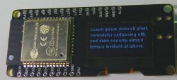
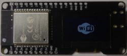
    Soon, on elektroda.pl, a WiFi module will appear with an ESP32 board and an OLED SSD1306 display. The ESP32 capabilities and the integration with Arduino are described here: ESP32 + Arduino . The English-language description of the integration is available here: ESP32 & Arduino on Windows .
    The SSD1306 display works on the I2C bus at the address 0x3C. SCL is connected to pin 4, SDA to I / O 5 - ESP32. On the board we find a USB UART converter, a 3.3V stabilizer and ESP32 terminals led to the edges of the board. The monochrome OLED display provides a very good contrast and a pleasant image appearance.


    ESP32 + OLED WiFi and BT module - commissioning, tests, description
    One of the libraries, eg U8g2, can be used to operate the display. After selecting Sketch-> Attach Library-> Manage Libraries, we can add or update U8g2. The configuration of the built-in display in U8g2 is as follows:
    U8G2_SSD1306_128X64_NONAME_F_SW_I2C u8g2 (U8G2_R0, / * clock = * / 4, / * data = * / 5, / * reset = * / U8X8_PIN_NONE);
    Set the board as Wemos ESP32: Tools-> WEMOS LOLIN32

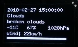
    ESP32 has more RAM than ESP8266 or ATmega328 and we can more conveniently process data in JSON format provided in the API of many systems. For example, the weather forecasts http://openweathermap.org/api and https://www.wunderground.com/weather/api or air quality data https://airly.eu/pl/api/ are available as JSON.
    Much of this data is available online for free, just register an account and receive your personal key.

    In the case of openweathermap http://openweathermap.org/price, after creating an account, we receive our key, after checking what ID has our city http://bulk.openweathermap.org/sample/city.list.json.gz (e.g. for Warsaw 7531926 ) we can send inquiries and present the weather forecast on the display.

    To conveniently process JSON data, add the ArduinoJson library to Arduino by searching for it in Sketch-> Attach library-> Manage libraries.

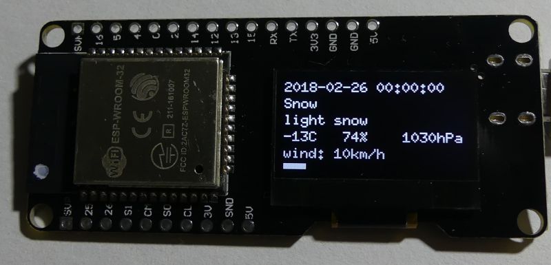
    We get the weather forecast for the following hours in a fairly simple way:
    ESP32 + OLED WiFi and BT module - commissioning, tests, description

    Below is an example of a simple code that you can adapt both to display the current weather forecast, as well as to virtually any data published by JSON. Instead of descriptions, you can enter a graphical representation of the weather forecast: https://openweathermap.org/weather-conditions

    Code: C / C++
    Log in, to see the code


    What ideas do you have for using a miniature WiFi module with ESP32 and a 128x64 OLED display?
    ESP32 + OLED WiFi and BT module - commissioning, tests, description ESP32 + OLED WiFi and BT module - commissioning, tests, description

    Cool? Ranking DIY
    Do you have a problem with Arduino? Ask question. Visit our forum Arduino.
    About Author
    TechEkspert
    Editor
    Offline 
    TechEkspert wrote 6246 posts with rating 4908, helped 16 times. Been with us since 2014 year.
  • ADVERTISEMENT
  • #2 17066733
    george2002

    Level 21  
    Everything was nice, but you could not use all the subtitles in Polish, only in English ... in short, did the author add anything to the code or just compiled it? :) ? what Flash and RAM capacity of this device because only dry data can see that more than Atmega or ESP8266 ...
  • #3 17066879
    TechEkspert
    Editor
    As I wrote, the ESP32 parameters and the integration method can be found in the linked material to the previously shared module.
    I wrote the code based on the available examples, there is nothing innovative there, it is a quick start with the module. The English weather descriptions are derived from the JSON data, and the comments make the material more international.
  • ADVERTISEMENT
  • #4 17067200
    atek000
    Level 18  
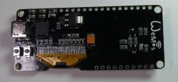
    I can see a small minus of this module, especially at the beginning as we want to play with everything and check everything. The display is on one side and the buttons are on the opposite. If you stick to the contact plate, there will be no access to the buttons. I just checked Aliexpress and there are modules with LCD, two buttons and a microUSB input on the same side, in addition, the price is identical.
  • #5 17067535
    piterek-23
    Level 33  
    atek000 wrote:
    I can see a small minus of this module, especially at the beginning as we want to play with everything and check everything. The display is on one side and the buttons are on the opposite. If you stick to the contact plate, there will be no access to the buttons.

    Buddy, you can plug this module into the breadboard so that the buttons and the USB socket will be behind the plate ;)
  • #6 17067583
    atek000
    Level 18  
    Sure I can, I know it and everyone who plays with such modules. My point is that everything on the same side would be more convenient though. If someone is interested and chooses from many available solutions, it is worth paying attention to this small detail. Besides, the module is very interesting, I have already ordered it for myself. Probably when it comes, I will play, I will do test connections and finally the module will end up in the drawer with others ;) .
  • #8 17071588
    futek2
    Level 19  
    Hello.
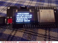
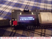
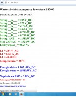
    I use the LOLIN ESP32 OLED module as MINI PV LOGER to my ES5000 inverter. Communication is via WIFI within 50 meters.
    Just a little computer.

    More details and program code on the link below.

    https://www.elektroda.pl/rtvforum/topic2734786-1530.html#17071028

    Best regards.
    Futek2
  • #9 17076245
    TechEkspert
    Editor
    A very nice use of the module as a remote display, WiFi is used or would ESP-Now make sense here?
  • #10 17076283
    futek2
    Level 19  
    Hello.
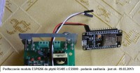
    The ESP8266 is installed in the ES5000 inverter and it has been in operation for almost a year.
    Power supplied by means of a 12VDC / 3.3VDC isolation converter.
    Photo attached.
    On ESP8266 it is written so soft that there is a web server to view the parameters from the inverter locally within a radius of about 50 meters.
    It also works on phones.
    Additionally, there is a data transfer from the inverter to the PV MONITOR server every 3 minutes.
    Photos attached.
    Soft on ESp8266 was written thanks to a lot of help from AKRAWIEC.
    And I have the LOLIN ESP32 OLED module thanks to the elektroda.pl forum.
    And at the beginning of getting to know it, I made a simple watch and then, as I had mastered the OLED display control, I went further.
    Now I am planning to do a MINI CO LOGER to have an overview of the parameters of the CO furnace anywhere in the building.

    I think that many colleagues also have interesting ideas for creating similar duets, i.e. ESP8266 with LOLINESP32 OLEG.

    Best regards.

    Futek2
  • #11 17076371
    Bullseye
    Level 27  
    I have a quick question, namely what are the differences between:
    1. Wemos LOLIN32 lite ESP32 v1.0 (MicroPython uploaded by default)
    2. NodeMCU ESP-32S v1.1

    According to the description and appearance, it is the same, with a different number of outputs, I do not need them, hence the question is whether there will be any difference for me when I take WEMOS instead of NODE (with time I will want to take the one with the display :) )
  • #12 17092294
    korrus666
    Level 40  
    There is a problem with the link:
    https://git.oschina.net/dfrobot/FireBeetle-ESP32/raw/master/package_esp32_index.json

    Namely, the json file that is being downloaded has an incorrect link to the Git repository.
    is:
    https://github.com/espressif/esp32-arduino
    and it should be
    https://github.com/espressif/arduino-esp32
    such a Czech mistake.
    Unfortunately, this causes a problem with updating the tiles.
  • #13 17146015
    rafcio_21
    Level 29  
    Hello, I bought this module from gadgets and I have a question whether this OLED is colored or only white inscriptions on a black background.
  • ADVERTISEMENT
  • #14 17146134
    futek2
    Level 19  
    Hello.
    The display in the ESP32 module with OLED is black and white, as in the earlier descriptions on the attached photos.
    https://www.elektroda.pl/rtvforum/topic3436298.html#17071588

    Colors can be inverted, but takes more mA.

    https://www.elektroda.pl/rtvforum/topic3432615.html
    You can also rotate the image to match the letters and numbers in the housing after installing the ESP32.


    Futek2
  • ADVERTISEMENT
  • #15 17436440
    futek2
    Level 19  
    Hello, interested in the topic.
    For a few days I have been struggling with the problem that I want to transfer the code from ARDUINO UNO to LOLIN ESP32 OLED. The program is practically compiling but it does not do what it should because I had to remediate a few lines of code in which there were TIMER registers. it would be like for ATMEGA238P
    And these are:

    a loop SETUP:
    TCCR1A = 0;
    TCCR1B = (1
  • #17 17437907
    futek2
    Level 19  
    I warmly welcome.
    Thanks TechEkspert for info.
    I am familiar with it, but it does not work in practice. I want to run the TDR meter according to this concept. The electronics are complete.
    https://forum.arduino.cc/index.php?topic=183770.msg1365676#msg1365676

    And now I found such info and maybe it will solve the problem.
    https://www.instructables.com/id/625-Nanosecond-Resolution-Timer-for-Any-Microcontr/
    Because I can't deal with registers on ESP32, I have no experience and the descriptions on the web also raise this problem, but the solutions on ESP32 are not described.
    For example, there is also a description, but no answer.
    https://www.esp32.com/viewtopic.php?t=5629
    Maybe it would be possible, and if not, I will have to write the entire program code from the beginning on ESP32.
    And I decided on this description because the ESP32 has a good processor and fast because 260Mhz, so it beats the uC ATMEGA238P and the accuracy of the measurement in searching for returns in cables would be good.
    According to the preliminary calculations, it would be around 10 cm in error.
    And there was a display that the device could be standalone and small, powered by a lithium battery.
    In the code on ESP32 I have made the website service and you can read the measurement results on the phone. I did it with the idea that the program code could also be run on ESP8266, which has no display.
    Because the tests on the ARDUINO UNO are not very good, the measurement error is about 1.5 meters despite the use of the TLV3501 comparator.
    Basic diagram also attached.
    And as it already looks like, the photo is attached.
    Attached I am sending a description of the principle of operation for those interested in the details.
    In the past it was not possible without the use of an oscilloscope and today it can be done safely with even good accuracy, for example, on the WEMOS LOLIN ESP32 OLED, which was available in the ELEKTRODY shop for points.
    But you should remember to add a quick comparator to the system, e.g. TVL3501, which is not expensive and accessible.

    Best regards.
    Futek2
  • #18 17443894
    TechEkspert
    Editor
    An interesting project, in this application, going down to the register level may pay off.

    It is worth showing up in DIY later.
  • #19 17444100
    futek2
    Level 19  
    Hello.
    I am slowly finishing the code, but without any register operations.
    But when I checked what impulses appear with the help of the LOGIC ANALYZER, it occurred to me that this device would also be possible to use to measure the time of the echo appearance.
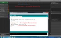
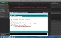
    When testing the ESP32 option, I measured the pulses with a time less than 1us using the LOGIC ANALYZER - photo in the connection.
    And then divide by 2 and help by i deceleration factor of the wave propagation in the wire depending on the insulation.
    But maybe one of the readers will support the topic.
    In the LOGIC program that supports the LOGIC ANALYZER, it is possible to install your own PLUGINs in which you can define practically whatever you want to show and calculate the LOGIC ANALYZER.
    But using ESP32 gives you more possibilities because there is no need for a PC.
    I am hopeful that the topic will develop and there is some helpful information on how to use timers on ESP32 registers and you only need 2 one to generate the pulse and the other to measure the time after which state 1 will appear from the comparator when the echo signal appears.
    I encourage readers to contribute to the topic.

    Best regards.
    Futek2
  • #20 17545454
    tos18
    Level 42  
    I would like to propose another way to initialize the oled display.
    In my case, the change made operations on oled take place at least twice as fast.
    So to the point
    is:
    Code: C / C++
    Log in, to see the code

    I suggest:
    Code: C / C++
    Log in, to see the code


    and the second shift
    is:
    Code: C / C++
    Log in, to see the code

    I suggest:
    Code: C / C++
    Log in, to see the code


    Please let me know if the change is also visible in your case.
  • #21 17546694
    TechEkspert
    Editor
    Thanks for posting the improvement. What do you think is the reason for acceleration, use of hardware resources, or more efficient generated code?
  • #22 17546765
    tos18
    Level 42  
    I bet on the use of hardware I2C - this is suggested by the declaration ... _HW _... and the need for a configured and running wire.h with an indication of the output numbers.
    But it may also be that wire.h is better at software I2C than U8G2 itself. I just noticed that he talked faster and I needed him to talk faster because the operations on the display slowed down the whole program.
    I am using U8G2log so there are many operations.

    Has anyone else noticed the acceleration?
  • #23 17551441
    futek2
    Level 19  
    Hello.
    Referring to what was described by col. tos18 I would like to ask if there was a possibility to do GPIO on ESP32, which could be read its 1/0 state using registers. To get fast reading GPIO status 25.
    Currently it does this with a code:

    ((REG_READ (0x3FF4403C) & BIT (25))! = 0);
    Before that, you must declare access to GPIO25:
    REG_WRITE (0x3FF44020, BIT (25));

    This operation takes about 0.6us and it would depend on me to get lower with time.
    I would also like to improve the code snippet

    if (((REG_READ (0x3FF4403C) & BIT (25))! = 0) == 0 && READY == false)
    {
    READY = true;
    }


    After that, I run the clock cycle register readout:

    command asm_ccount ();

    And this is how it is declared:
    static inline unsigned long asm_ccount (void)
    {
    unsigned long r;
    asm volatile ("rsr% 0, ccount": "= r" (r));
    return r;
    }


    It is also possible to read the clock cycles using:
    ESP.getCycleCount ();

    Using both of these possibilities, the clock cycle readings do not notice any major differences.
    The capacity of the clock's cycle counter is 4294967295 . .
    Enclosed, I am sending a list of registers that I relied on for ESP32.
    The code on which it rides was on the ATMEGA2378P and it looked like this:

    TCCR1A = 0;
    TCCR1B = (1
  • #24 17558520
    futek2
    Level 19  
    Hello, interested in the topic.
    In recent days, after reading the ESP32 parameters, I found out that there are GPIO in a different group of registers and they are GPIO 32 - 39 and I did such tests that on ESP32 I made a simple pulse generator with a short time, i.e. 1us and sequentially changing the GPIO number that I connected with the sending GPIO I controlled these pulses with the LOGIC ANALYZER times of appearance of the control pulse as a response to the interrupt from the selected GPIO INPUT.
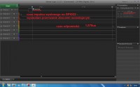
    My tests have shown that the fastest in response is GPIO32 responds to impulses with a duration of about 83ns, but the response appears after 1.875us. Photos with measurement results attached.

    GPIO 32 is the first in a different register group with the address 0x3FF44040 .
    Control pulse time 41ns.
    GPIO 34 - 39 are systemically only INPUT on board ESP32.
    I pass this info on because it may be useful to other people interested in using ESP32 for their construction.
    Futek2

Topic summary

The discussion revolves around the integration and functionality of an ESP32 module with an OLED SSD1306 display, focusing on its commissioning, testing, and programming. Users share insights on the module's specifications, including its I2C communication setup (SCL on pin 4, SDA on pin 5) and the use of libraries like U8g2 for display control. Concerns are raised about the physical layout of the module, particularly the positioning of buttons and the display, which may hinder accessibility when mounted on a breadboard. Users also discuss various applications, such as using the module for remote displays and data logging with inverters. Additionally, there are inquiries about differences between ESP32 models and issues related to GPIO register access for faster operations. Suggestions for optimizing display initialization and code efficiency are also provided.
Summary generated by the language model.
ADVERTISEMENT