Hello again, everyone.
Today I will try to describe to you once again the TEA5767 radio module from NXP, but today it will be based on a more extensive set and will also be about reading information from this module.
Below you have a link to the previous description:
https://www.elektroda.pl/rtvforum/topic3449784.html#17159497
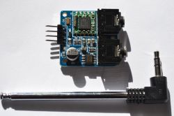
The set described today, apart from the TEA5767, has an amplifier built on the TDA1308 chip also from NXP, two headphone sockets - one for the audio output, the other for the antenna socket. Unfortunately, we have a headphone amplifier here, so we can't connect speakers directly here.
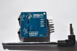
The supply voltage is 5VDC, current consumption is about 18mA. The system includes a D1 diode which acts as a protection against reverse polarity of the supply voltage. On the board, we have a goldpin connector for power connection and communication, described as + 5V, SDA, SLC, GND.
The dimensions of the whole with the goldpin connector are 40x30x10mm.
The set is sold with a telescopic antenna, which is 24cm when unfolded. Prices in China with shipping start from $ 3.23, Allegro has only one offer with this module for PLN 48 with shipping.
It was supposed to be about reading the information provided by the module, so to the point.
Below is a program written in BASCOM.
Comparing it to the previous program, we have here an added part reading five bytes from TEA5767 and changed settings in write mode - after sending five bytes in write mode, five bytes in read mode are read. The idea is to force the radio to search for a radio station, where it will start to search the frequency downwards or upwards from the frequency given to it and stop after certain conditions are met - all this is written in byte three in the write mode, we just have to remember that in byte turn on SEARCH MODE first - bit 6.
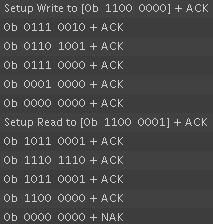
In the picture below we can see the reading from I2C - what was sent and received from the TEA5767 module (part of the program - station_3). This was read using the SALEAE logic analyzer plugged into the SDA and SLC wires (remember about common ground) between the ZL2AVR and TEA5767 development kit.
Let's look at the documentation for the byte description in read mode. Below is a fragment of documentation where we have a description of bytes in read mode and an address for working in read mode.
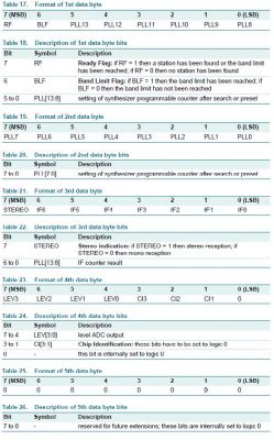
The first two bytes contain information such as:
First byte
- bit 7 - whether the station has been found or the frequency limit has been reached;
- bit 6 - whether the frequency limit has been reached;
- bit 5 to 0 - PLL 13 to 8
Second byte
- bit 7 to 8 - PLL7 to 0
As you can see - the module found a radio station, and the frequency limit was not reached. If no station meeting the given conditions is found, the module will stop at the lowest or highest frequency (depending on whether it is looking up or down), i.e. 87.5 or 108MHz, and bit 6 of the first byte will be equal to 1. PLL in this case is 11000111101110 written in the binary system, which after conversion to the decimal system gives us 12782. Using the following formula:

After the transformation, we get the following formula, where from the PLL we can calculate the frequency of the received station, the frequency with this RMF load:
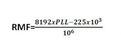
Therefore, it follows from the above that our module, when searching for stations, stopped at the frequency of 104.485144 or 104.5MHz.
In the same way, we can calculate the frequency from which the module was looking for a radio station. PLL here is 11001001101001, or 12905, which gives the frequency 105.5MHz after the conversion according to the formula.
Byte three, bit 7 tells us whether the station is received in stereo or in mono.
From the reading we have 1, which means in this case that the station being received is in stereo.
According to the documentation for the described fourth byte in read mode, bits 7 to 4 are the ADC level. In our case, the value read is 1100 (bin) = 12 (dec).
According to the settings, our module was supposed to search "down" from the set frequency 105.5MHz - byte 3 bit 7 (0 - searching down, 1 - searching up).
The search was to be stopped on a high signal, ADC output level = 10, byte 3 bits 6 and 5 (Search Stop Level).
Summarizing all this, the module was to search for stations, starting from the 105.5MHz frequency, it was to look down and stop at the station with the ADC level not lower than 10. The module searched for stations with ADC level 12 on the frequency 104.5 so it was assigned conditions met. We also have information that this station is received in stereo.
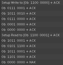
Here is an example of searching for another station, this time with ADC = 13, reception also in stereo. Searching from 104MHz and finding it at 103.3MHz (program part - station_2).
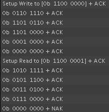
Below is an example of searching up and with lower ADC level (program part - station_1). You can see here that the search was from 98MHz and stopped at 99.1MHz, the station is not received in stereo and its signal strength is 7 assuming the search is at a minimum of 7.
By changing the program, one could obtain a range search, but it would have to be taken into account that the module starts searching from the frequency given to it and stops when it meets the conditions given to it, but the conditions are not always met - a radio station. Sometimes it is some kind of hum in the ether, so the search should be resumed from the moment of stopping, i.e. the PLL variable should be replaced with what was read after the search was stopped - otherwise we will always search from the same frequency and always stop in the same place.
I put this receiver in the car for testing. When stationary, it receives radio stations quite well, although they are not always in stereo. I took it for a ride and on the antenna from the set while driving, the quality of reception decreases, after adding a meter long cable it improves, but it is not the same as when stationary, although sometimes the signal is very good. I think that by connecting this receiver to the installation of a car antenna, reception would improve significantly, but I wouldn't count on it gaining mobility. I would say this module is more of a desktop application.
I think that if someone wants to play with such a radio receiver, it is worth spending less than $ 4, the advantage of this module is quite simple operation via I2C.
It should also be remembered that this module does not remember what it was sent, soafter disconnecting the power, we will not hear anything until we send it again five bytes in write mode.
Today I will try to describe to you once again the TEA5767 radio module from NXP, but today it will be based on a more extensive set and will also be about reading information from this module.


Below you have a link to the previous description:
https://www.elektroda.pl/rtvforum/topic3449784.html#17159497
The set described today, apart from the TEA5767, has an amplifier built on the TDA1308 chip also from NXP, two headphone sockets - one for the audio output, the other for the antenna socket. Unfortunately, we have a headphone amplifier here, so we can't connect speakers directly here.
The supply voltage is 5VDC, current consumption is about 18mA. The system includes a D1 diode which acts as a protection against reverse polarity of the supply voltage. On the board, we have a goldpin connector for power connection and communication, described as + 5V, SDA, SLC, GND.
The dimensions of the whole with the goldpin connector are 40x30x10mm.
The set is sold with a telescopic antenna, which is 24cm when unfolded. Prices in China with shipping start from $ 3.23, Allegro has only one offer with this module for PLN 48 with shipping.
It was supposed to be about reading the information provided by the module, so to the point.
Below is a program written in BASCOM.
Code: VB.net
Comparing it to the previous program, we have here an added part reading five bytes from TEA5767 and changed settings in write mode - after sending five bytes in write mode, five bytes in read mode are read. The idea is to force the radio to search for a radio station, where it will start to search the frequency downwards or upwards from the frequency given to it and stop after certain conditions are met - all this is written in byte three in the write mode, we just have to remember that in byte turn on SEARCH MODE first - bit 6.
In the picture below we can see the reading from I2C - what was sent and received from the TEA5767 module (part of the program - station_3). This was read using the SALEAE logic analyzer plugged into the SDA and SLC wires (remember about common ground) between the ZL2AVR and TEA5767 development kit.

Let's look at the documentation for the byte description in read mode. Below is a fragment of documentation where we have a description of bytes in read mode and an address for working in read mode.

The first two bytes contain information such as:
First byte
- bit 7 - whether the station has been found or the frequency limit has been reached;
- bit 6 - whether the frequency limit has been reached;
- bit 5 to 0 - PLL 13 to 8
Second byte
- bit 7 to 8 - PLL7 to 0
As you can see - the module found a radio station, and the frequency limit was not reached. If no station meeting the given conditions is found, the module will stop at the lowest or highest frequency (depending on whether it is looking up or down), i.e. 87.5 or 108MHz, and bit 6 of the first byte will be equal to 1. PLL in this case is 11000111101110 written in the binary system, which after conversion to the decimal system gives us 12782. Using the following formula:

After the transformation, we get the following formula, where from the PLL we can calculate the frequency of the received station, the frequency with this RMF load:

Therefore, it follows from the above that our module, when searching for stations, stopped at the frequency of 104.485144 or 104.5MHz.
In the same way, we can calculate the frequency from which the module was looking for a radio station. PLL here is 11001001101001, or 12905, which gives the frequency 105.5MHz after the conversion according to the formula.
Byte three, bit 7 tells us whether the station is received in stereo or in mono.
From the reading we have 1, which means in this case that the station being received is in stereo.
According to the documentation for the described fourth byte in read mode, bits 7 to 4 are the ADC level. In our case, the value read is 1100 (bin) = 12 (dec).
According to the settings, our module was supposed to search "down" from the set frequency 105.5MHz - byte 3 bit 7 (0 - searching down, 1 - searching up).
The search was to be stopped on a high signal, ADC output level = 10, byte 3 bits 6 and 5 (Search Stop Level).
Summarizing all this, the module was to search for stations, starting from the 105.5MHz frequency, it was to look down and stop at the station with the ADC level not lower than 10. The module searched for stations with ADC level 12 on the frequency 104.5 so it was assigned conditions met. We also have information that this station is received in stereo.
Here is an example of searching for another station, this time with ADC = 13, reception also in stereo. Searching from 104MHz and finding it at 103.3MHz (program part - station_2).

Below is an example of searching up and with lower ADC level (program part - station_1). You can see here that the search was from 98MHz and stopped at 99.1MHz, the station is not received in stereo and its signal strength is 7 assuming the search is at a minimum of 7.

By changing the program, one could obtain a range search, but it would have to be taken into account that the module starts searching from the frequency given to it and stops when it meets the conditions given to it, but the conditions are not always met - a radio station. Sometimes it is some kind of hum in the ether, so the search should be resumed from the moment of stopping, i.e. the PLL variable should be replaced with what was read after the search was stopped - otherwise we will always search from the same frequency and always stop in the same place.
I put this receiver in the car for testing. When stationary, it receives radio stations quite well, although they are not always in stereo. I took it for a ride and on the antenna from the set while driving, the quality of reception decreases, after adding a meter long cable it improves, but it is not the same as when stationary, although sometimes the signal is very good. I think that by connecting this receiver to the installation of a car antenna, reception would improve significantly, but I wouldn't count on it gaining mobility. I would say this module is more of a desktop application.
I think that if someone wants to play with such a radio receiver, it is worth spending less than $ 4, the advantage of this module is quite simple operation via I2C.
It should also be remembered that this module does not remember what it was sent, soafter disconnecting the power, we will not hear anything until we send it again five bytes in write mode.
Cool? Ranking DIY


