logo elektroda
logo elektroda
X
logo elektroda

How to connect the Koogeek Dimmer Switch to an installation with L, N, PE?

chadrain 1311 9
Best answers

Can I connect a Koogeek dimmer switch that needs L, L1/L2, and N to a standard wiring box with brown L, blue N, and green-yellow PE, and how should L1 be wired?

No, not as a normal L/N/PE installation, because the box shown does not actually provide N there and the dimmer needs N in the box; the green-yellow wire must not be used as a live conductor. In the thread, the wires in that box are described as phase only, with the blue and green-yellow conductors already being used as live conductors rather than neutral/PE [#17563601][#17563631] If you can bring a real N and PE to the box, the device can be connected only to one circuit, but the protective yellow-green wire still cannot be used as a switched conductor [#17563715] The wiring between the switch and the junction box should be replaced if you want a proper installation [#17563719]
AI summary based on the discussion. May contain errors.
ADVERTISEMENT
This content has been translated flag-pl » flag-en View the original version here
  • #1 17563586
    chadrain
    Level 2  
    Posts: 4
    Good afternoon,
    I am trying to ascertain whether a smart switch/dimmer will be compatible with my electrical installation and if so how to connect it correctly.

    This is my installation, which is typical:

    brown cable - phase L,
    blue cable - neutral N,
    green-yellow cable - protective PE

    How to connect the Koogeek Dimmer Switch to an installation with L, N, PE?IMG_646...JPG (1014.53 kB)You must be logged in to download this attachment. .

    https://mobidick.pl/sklep/koogeek-dimmer-switch/

    and such a switch has a diagram:

    How to connect the Koogeek Dimmer Switch to an installation with L, N, PE?08-2.jpg (52.58 kB)You must be logged in to download this attachment. .

    Is this compatible?

    How to connect this L1 ?

    Thank you very much in advance!
  • ADVERTISEMENT
  • Helpful post
    #2 17563601
    ta_tar
    Level 41  
    Posts: 6483
    Help: 699
    Rate: 2052
    This is probably a two-key switch. If so, then unfortunately you only have a phase there (possibly on the brown wire) and then you feed this phase to one consumer via the blue wire and to the other consumer via the green-yellow wire. The latter is unacceptable as the green/yellow wire is only used for protection. From this it follows that you have no N in the box and your circuit breaker needs it.
  • ADVERTISEMENT
  • Helpful post
    #3 17563631
    mawerix123
    Level 39  
    Posts: 4150
    Help: 482
    Rate: 951
    chadrain wrote:
    This is my installation, which is typical:

    brown cable - phase L,
    blue cable - neutral N,
    green-yellow cable - protective PE
    .

    In this case you have:

    brown cable - phase L
    blue cable - phase L'
    green-yellow cable - phase L'
  • #4 17563704
    chadrain
    Level 2  
    Posts: 4
    Thank you very much for your help

    So I understand that in my case it is

    L - phase

    L1 - to one lamp
    L2 to the other lamp

    I am missing N
    and PE

    Do I understand this correctly?

    So that it is a rather wild installation, substandard and not very safe?

    Is there any way around this, some kind of patent, other than changing the whole installation?

    Thank you in advance
  • Helpful post
    #5 17563715
    ta_tar
    Level 41  
    Posts: 6483
    Help: 699
    Rate: 2052
    If you have the possibility to draw the N and PE wire to this box then you can connect this novelty but only to one circuit as you cannot use this yellow-green wire.
  • ADVERTISEMENT
  • Helpful post
    #6 17563719
    mawerix123
    Level 39  
    Posts: 4150
    Help: 482
    Rate: 951
    Yes, you understand correctly.
    Is the wild installation... hmm.
    The wire from the switch to the junction box should be replaced.
  • ADVERTISEMENT
  • #7 17563850
    Waski85
    Level 13  
    Posts: 117
    Help: 4
    Rate: 22
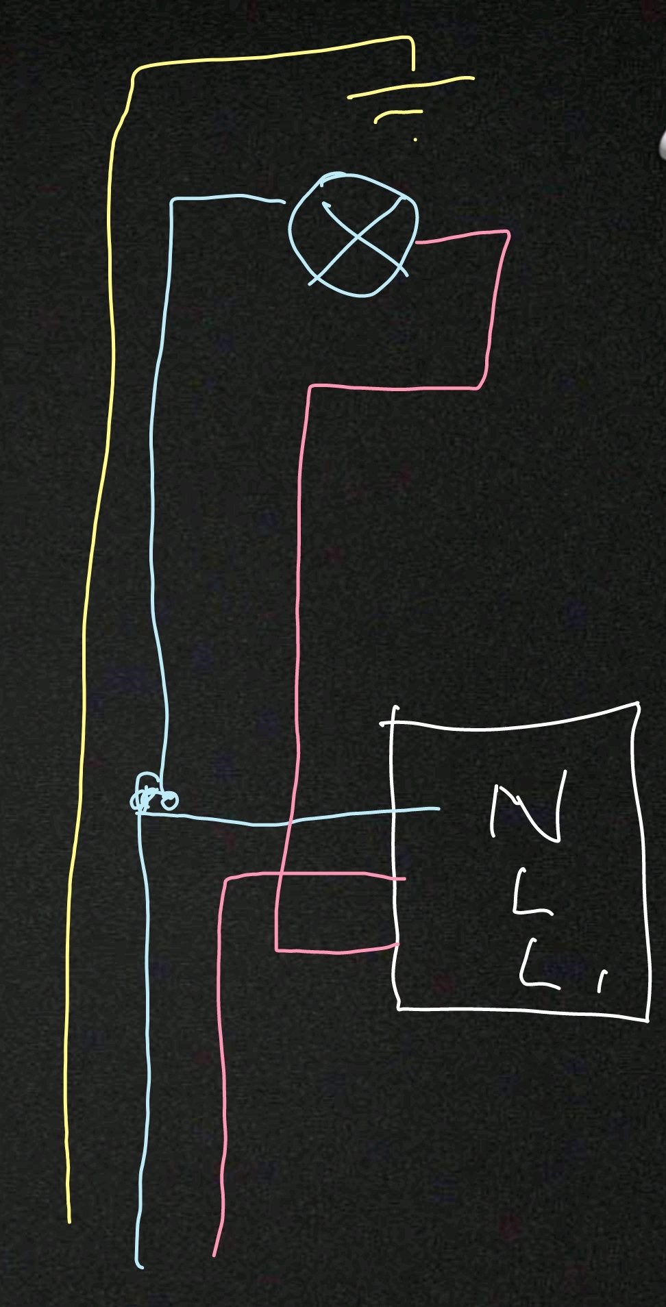
    And shouldn't it be like this? Probably some American invention with this L1.

    How to connect the Koogeek Dimmer Switch to an installation with L, N, PE? .
  • #8 17563873
    ta_tar
    Level 41  
    Posts: 6483
    Help: 699
    Rate: 2052
    And what don't you like about your own almost good drawing (no protective to the N, L ,L`-square point).
  • #9 17563884
    Waski85
    Level 13  
    Posts: 117
    Help: 4
    Rate: 22
    Sorry, the author confused me by writing that his installation is "typical". I only now enlarged the picture and saw what was done there.
  • #10 17563920
    chadrain
    Level 2  
    Posts: 4
    Thank you very much for your help,
    I hope it will also be useful to someone else, because there will probably be more and more such gadgets vs Polish installations
    Best regards

Topic summary

✨ The discussion addresses the compatibility and wiring of the Koogeek Dimmer Switch with a typical electrical installation featuring brown (phase L), blue (neutral N), and green-yellow (protective earth PE) cables. It is clarified that the existing installation lacks a proper neutral wire in the switch box, as the blue and green-yellow wires are incorrectly used as phase conductors, which is unsafe and non-standard. The green-yellow wire must not be used as a phase conductor since it is reserved for protective earth. The Koogeek Dimmer Switch requires a neutral connection for proper operation, which is missing in this setup. The L1 terminal on the switch corresponds to one lamp load, while L2 would be for another, but without a neutral, the device cannot be correctly connected. The consensus is that the current installation is substandard and potentially hazardous. The recommended solution is to run a neutral and protective earth wire to the switch box to enable safe and compliant connection of the smart dimmer. No workaround or "patent" solution is advised other than upgrading the wiring to meet electrical safety standards.
AI summary based on the discussion. May contain errors.
ADVERTISEMENT