logo elektroda
logo elektroda
X
logo elektroda

Configuration of ESP8266 as UDP server with RS232 - IP 10.10.2.1, port 22000, AT?

heyka 5412 78
ADVERTISEMENT
Treść została przetłumaczona polish » english Zobacz oryginalną wersję tematu
  • #31 17830061
    heyka
    Level 17  
    Dear colleagues, I am grateful for your help and patience.

    But somehow it doesn't occur to me that I need to paste so much code into the AP UDP module.
    I use AT commands to set up:
    - AP operating mode
    - UDP transmission
    - IP no.
    - listening port number
    - data transfer rate on RS232
    and that everything arriving at the module is sent to RS232.
    On the other hand, programming the module via Arduino adds so many additional things.

    Added after 18 [minutes]: .

    what I mean is whether this set IP address is the address of the module working as a station or is it the address of the module when it works as a UDP server.
  • ADVERTISEMENT
  • #32 17830116
    khoam
    Level 42  
    heyka wrote:
    On the other hand, programming the module via Arduino adds so many extra things.
    .
    Are you referring to any specific code you are already testing? If so, please post that code here - give yourself a chance to help.

    heyka wrote:
    what I'm referring to is whether this set IP address is the address of the module working as a station or is it the address of the module when it is working as a UDP server.
    .
    Is the IP address of the network interface of a device that can act as both client and server.
  • #33 17830117
    kaczakat
    Level 34  
    This is easier for me, not necessarily for you. AT commands do exactly the same thing as commands in Arduino. Unfortunately you are unlikely to achieve what you wrote with AT commands, because their use is limited to what was intended by the author of that firmware. Well, unless you don't need the fact that the module will respond once with what it got on the UART and otherwise with the same message. Likewise the soft recommended by @khoam doesn't do exactly what you want, but here you already have access to it, it prints the IP from where the message came from? You don't need it, it's a snap in the comment. AT commands didn't pop into your head somewhere either, you had to learn them.
    Helpful post? Buy me a coffee.
  • #34 17830220
    heyka
    Level 17  
    I think I got it all wrong, the key is to know the libraries and the commands within them

    Code: C / C++
    Log in, to see the code


    Can you recommend me any site with documentation for them?
  • #35 17830259
    khoam
    Level 42  
    heyka wrote:
    Will you please recommend me a site with documentation for them?


    You might want to have a look at the manual attached for a start. There's a lot more in there than you need, but I'm sure a lot of things will become clear. The manual is written in terms of using the ESP8266 with the Arduino HAL.
  • #37 17830800
    heyka
    Level 17  
    I bought an ESP programming module https://opiniolog.com/pl/read/3636/, but I can't upload the program to the board, AT commands are accepted by the module, but the program from Adruino is not, I added a switch to connect the GPIO to GND.
  • ADVERTISEMENT
  • #38 17830831
    khoam
    Level 42  
    heyka wrote:
    and the program from Adruino does not want it, I added a switch to connect the GPIO to GND.
    .

    I take it you mean GPIO-0? What board do you have selected in the Arduino IDE? It should be for "Generic ESP8266 Module". Flash Mode should be set as QIO, Flash Size as 1M (no SPIFFS).
    If you manually enter programming mode by shorting GPIO-0 to ground, the Reset Method parameter should be set to "none".

    Ideally, you should give a screenshot, from the "Tools" menu :) .
  • #39 17830856
    krzbor
    Level 27  
    And have you watched this: Link Looks nice and simple.
  • ADVERTISEMENT
  • #40 17830888
    heyka
    Level 17  
    I can't take a snapshot because the tool window collapses for me.
  • #41 17830896
    kaczakat
    Level 34  
    heyka wrote:
    I bought one for ESP programming
    Unfortunately someone has misled you, I have seen these dongles in two types, the one without a switch is only for communication mode, the one with a switch on the side can work as a programmer (it connects this GPIO 0 to GND) or as a UART-USB bridge. This is in fact described below in your link. By the way, you could have bought a NODE MCU or a WEMOS mini, at least the shipping wouldn't have doubled the order amount, and you program them without trivialising any switches. You connect to the USB port after shorting 0 with GND, you can also do a short, reset, after 1s it is in programming mode.
    Helpful post? Buy me a coffee.
  • #44 17830992
    khoam
    Level 42  
    heyka wrote:
    I bought the programmer exactly from this page https://nettigo.pl/products/adapter-usb-do-modulow-esp8266-01,,,,, I added the button only that I put a resistor 470 in series with it.
    .

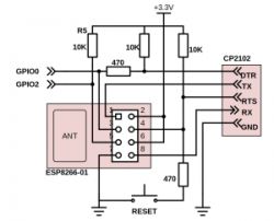
    In the case of ESP-01 programming, it is better to buy a regular USB-UART converter and make an auto-reset circuit, as shown below on the diagram (the RESET button is only needed if the chip hangs up). Then, you will be able to program the ESP-01 automatically, as in the case of standard Arduino boards (reset in ck mode and automatic entering/exiting programming mode). It works flawlessly with various UART-USB converters.

    Configuration of ESP8266 as UDP server with RS232 - IP 10.10.2.1, port 22000, AT? .
  • #46 17831326
    khoam
    Level 42  
    heyka wrote:
    you probably still need a 3.3V to 5V logic level converter.


    Not needed. In this USB-UART converter you can select either 3V3 or 5V logic with a jumper.
  • #47 17842083
    heyka
    Level 17  
    I have this code

    Code: C / C++
    Log in, to see the code


    The code works, except that the ESP module works in ST mode it connects to the computer via the router, now how do I rework this to make the ESP work in AP mode?
  • #49 17842180
    heyka
    Level 17  
    Code: C / C++
    Log in, to see the code
    .

    I came up with something like this, the AP works, when I connect the computer to the network created by the ESP module, an IP number has been given to the computer, so the connection is there, but when I send something from this computer to the module address nothing appears on the port.
  • #50 17842198
    khoam
    Level 42  
    heyka wrote:
    but when I send something from this computer to the module address, nothing appears on the port.
    .
    What specifically are you sending? Your program only reports UDP packets received.
  • #51 17842222
    heyka
    Level 17  
    Works :) .

    I forgot to give:

    Code: C / C++
    Log in, to see the code


    First battle won.

    Added after 1 [minute]:

    khoam wrote:
    heyka wrote:
    but when I send something from this computer to the module address nothing appears on the port.
    .
    What specifically are you sending? Your program only reports UDP packets received.
    .

    I tried sending some strings to the module from my computer and a program I wrote from my smartphone.

    Added after 16 [minutes]:

    I don't quite understand this piece of code

    Code: C / C++
    Log in, to see the code
  • Helpful post
    #52 17842387
    khoam
    Level 42  
    When data is loaded into the 'incomingPacket' character buffer, it writes a '0' character after the last character loaded - this is known as the text string terminator.
  • #53 17843417
    heyka
    Level 17  
    Code: C / C++
    Log in, to see the code
    .

    This is what I cannot understand, Udp.read writes the received data to the buffer, but how is the number of buffer elements len calculated?
    len is of type int, e.g.

    int len = "test;

    in this case len = 4 ?

    Added after 8 [minutes]:

    And now the next stage.

    I connect the ESP module via Uart to the Arduino board, the arduino sends me data ( strings) via Uart, how do I send it via ESP over WiFi to a specific address, port using UDP, I suspect you need to use the code below, just how do I "catch" into replypacket the data received via UART?

    Code: C / C++
    Log in, to see the code
    .
  • #55 17843690
    khoam
    Level 42  
    heyka wrote:
    Udp.read writes the received data to the buffer
    .
    and returns an int value, which is equal to the amount of data loaded (single bytes).

    Added after 7 [minutes]: .

    heyka wrote:
    I connect the ESP module via Uart to the Arduino board, the arduino sends me data ( strings) via Uart, how do I send it via ESP over WiFi to a specific address, port using UDP, I suspect you need to use the code below, just how do I "catch" into replypacket the data received via UART?
    .

    I think you should look at the WiFiUDP class methods in detail: Link .
  • #56 17844503
    heyka
    Level 17  
    kaczakat wrote:
    I uploaded the already working code to you a couple of days ago, just inserted a delay(5000) because I was typing the answers from my finger.


    Actually, it's just that a few days ago it was black magic for me, and now I'm starting to understand the code.

    Added after 11 [hours] 17 [minutes]:

    Hi everything works as I wanted, I have a question about the following part of the code:

    Code: C / C++
    Log in, to see the code
    .
    do i understand this correctly
    - checking if something has arrived via uart
    - if yes, I put the first received character into the first element of the buffer
    - if the buffer is big enough I increase the index i2
    - read the received character into the second buffer element, why is it the second received character and not the first again, after reading the first character from the received string, is the first character automatically deleted?

    One more thing I need to do in the code for the ESP8266 module:
    - I send a command from a smartphone e.g. ON I expose a state of 1 on the GPIO but for say 5 minutes and then the state of the GPIO changes to 0, but while this lasts for 5 minutes I would like to interrupt this time e.g. with an OFF command. Delay is out because it is a blocking function
  • #57 17845433
    khoam
    Level 42  
    heyka wrote:
    - if the buffer is large enough then I increase the index i2
    .
    And where is the initial 'i2' value reset and set? I assume you somehow control the index range for the 'buf2' buffer.

    heyka wrote:
    I send a command from a smartphone e.g. ON puts a state of 1 on the GPIO but for say 5 minutes and then the GPIO state changes to 0, but while this lasts for 5 minutes I would like to interrupt this time e.g. with an OFF command. Delay is out because it is a blocking function
    .
    You can use millis() to count down the time in a loop.
  • #58 17845528
    kaczakat
    Level 34  
    In the serial event I've thrown you a ready-made function from the Arduino to receive a line of text, converted to char arrays (because that's how the UDP ESP prefers it). The only inconvenience is that you have to call it in ESP, in UNO the RX interrupt does it.
    Helpful post? Buy me a coffee.
  • #59 17846051
    heyka
    Level 17  
    khoam wrote:
    .
    And where is the 'i2' initial value zeroed and set? I assume you somehow control the index range for the 'buf2' buffer.

    .

    Code: C / C++
    Log in, to see the code
    .

    The variable is I2 is reset to zero when buf 2 is sent.

    Added after 4 [hours] 39 [minutes]: .

    Configuration of ESP8266 as UDP server with RS232 - IP 10.10.2.1, port 22000, AT? .

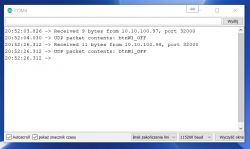
    I have this problem, I send a string from my PC to the module and it has 9 bytes, I send an identical string from my smartphone to the module and it has 11 bytes, I suspect that the smartphone program is appending invisible characters to the string being sent, probably CR and LF, how to make the comparison:
    Code: C / C++
    Log in, to see the code
    .

    where incomingPacked arrives as btnW1_OFF plus CR character plus LF character?

    Added after 40 [minutes]:

    khoam wrote:
    .
    heyka wrote:
    I send a command from a smartphone e.g. ON I get a state of 1 on the GPIO but for say 5 minutes and then the state of the GPIO changes to 0, but while this lasts for 5 minutes I would like to interrupt this time e.g. with an OFF command. Delay is out because it is a blocking function
    .
    You can use millis() to count down the time in a loop.


    I don't really know how to do this :( .
  • ADVERTISEMENT
  • #60 17847151
    khoam
    Level 42  
    heyka wrote:
    it appends invisible characters to the sent string probably CR and LF, how to make the comparison:

    if (!strcmp(incomingPacket, "btnW1_OFF"))

    where incomingPacket arrives as btnW1_OFF plus CR character plus LF character?


    You can use the strncmp() function:
    Code: C / C++
    Log in, to see the code
    .
    As they will not be docked, this should also work ;) .

    Added after 2 [minutes]:

    heyka wrote:
    I don't really know how to do this
    .
    Well, why don't you take a look here ?

Topic summary

The discussion revolves around configuring the ESP8266 module to function as a UDP server with a specific IP address (10.10.2.1) and port (22000), while also facilitating RS232 communication. Users explore the feasibility of using AT commands for setup, troubleshooting connection issues, and the limitations of the AT firmware. Several users share their experiences with command sequences, firmware versions, and the necessity of using Arduino for more complex configurations. The conversation highlights the importance of setting the correct operating mode (AP or Station), managing IP addresses, and handling incoming and outgoing data through UDP. Additionally, users discuss programming the ESP8266 using Arduino IDE, including code snippets for establishing UDP communication and responding to UART data.
Summary generated by the language model.
ADVERTISEMENT