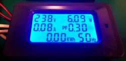
Panel meter of power consumption / consumption of electricity type P06S-20 and P06S-100
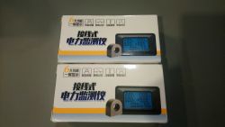
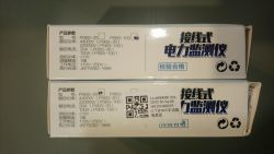
I received the above two power / energy meters for testing. They are identical in appearance, the only difference is the transformer attached to the stronger version. The dimensions of the module are 85x47 mm (part recessed into the housing), depth: 24 mm, the front panel dimensions are 90x55 mm, and the display 55x30 mm.
The weaker version (20 A / 4.4 kW) is equipped with a measuring shunt with a resistance of 3 m?, while the more powerful version (100 A / 22 kW) has an external current transformer with a ratio of 2000: 1 (or if you prefer 50 A / 25 mA) type DL-CT10CL. The transformer itself, according to the manufacturer, is adapted to measure the current with an intensity not exceeding 150 A. The power consumption of the meter is below 1 W. The meter is equipped with one button with which we can turn on or turn off the backlight, set the power overload alarm and reset the energy meter . The function is selected by holding the button for various times. However, there is no need to worry as the time differences are so long that the risk of accidentally erasing the energy meter is negligible. It is worth mentioning that the meter maintains its indications after disconnecting the power supply. However, it does not retain the screen backlight status - each time after a power failure, it starts with the backlight on.
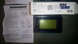
In the box, in addition to the meter and, if necessary, a transformer, we find a modest instruction manual, printed on a sheet of (more or less) A6 size. There is an English version on one side of the page and a Chinese version on the other.
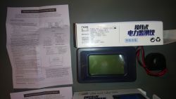
Both meters are based on the same PCB, differing only in the configuration of the resistors. In the 20 A version, these are two 6 m? resistors, size 2512, connected in parallel, forming the measuring shunt, and in the 100 A version (equipped with a transformer) it is a 1 ? resistor, size 0603. With a maximum current of 20 A, a voltage of 60 will be created on the shunt. mV, which will give 0.6 W per resistor (resistors of this size can dissipate 1 W). In the version with a transformer, at a maximum current of 100 A, a current of 50 mA will flow through the shunt, which will correspond to a voltage drop of 50 mV and a power of 2.5 mW, which the 0603 resistor should easily handle. The heart of the system is a specialized HT5019 microcontroller. It is a dedicated system for building single-phase power meters, based on the M0 kernel, with 128 KB of FLASH memory. The second chip present on the board (VK1621B) is the LCD driver (32x4). The electronics are powered by a primitive transformerless power supply, made of a capacitor and a resistor. There is no protection whatsoever for this power supply (not counting the resistor). I also suggest removing the board from the housing and cleaning it, because in both meters I found flux residues (mainly from the display side) and, what's worse, droplets of solder.
View after removing the back cover:
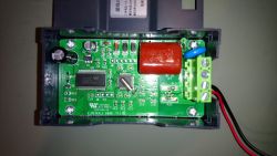
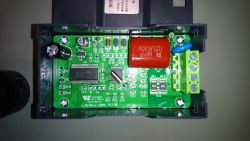
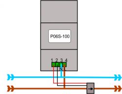
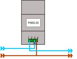
The connection of both modules is very simple - they are equipped with a solid screw connection, the two terminals of which, labeled L and N, are used to connect the power supply. In the 20 A version, the receiver is connected between the L terminal and the "1" terminal (the shunt is on the N wire). In the case of the version with a transformer (connected to terminals "1" and "2"), the direction of installing the transformer on the wire is important - there is an arrow on it, which should point in the direction of "zero" (L -> N). The opposite assumption will result in the lack of indications of active power and power factor.
The workmanship of the meters is not overly solid, but the casing does not seem to fall apart in your hands. Unfortunately, it is impossible to talk about any water / dust resistance of this meter. The button, which is a micro-switch protruding through the hole in the housing (without any key / cover), also hurts a bit. Another issue is the lack of the CE mark ... it seems to be irrelevant, but without this mark, the product cannot be marketed in the EU. I do not know if it is a question of my copy, but the 20 A version has a clearly worse display - it has very small viewing angles, and after turning on the backlight it becomes practically unreadable. In the 100 A version (also my previously purchased copy) the display is perfectly legible, both without and with backlight:
The device does not have any certificates, and the manufacturer does not even specify the accuracy of the measurements. The resolution of the indications is as follows:
voltage: 1V
power: 0.01 W (below 100 W)
current: 0.01 A (below 10 A)
power factor: 0.01 (1%)
energy: 0.01 kWh (up to 1000 kWh)
frequency: 1 Hz
The values in parentheses are the limit of the lowest measuring range, higher values can be measured but with reduced resolution.
For the purposes of the tests, I improvised a measuring stand in which I connected both meters in series:
As a reference, I used a GB202 type power meter and two multimeters (UT-139C for current measurement and AN8008 for voltage measurement).
The first test consisted of connecting a load in the form of a 40W bulb:
It might seem that the power factor readings basically disqualify my "reference" meter, but swapping the circuit so that the GB202 was connected last made the results agree:
BG202 (40 W bulb):
U = 234.3 V.
I = 0.179 A
P = 42.8 W.
PF = 1.00
Thus, in subsequent tests, the GB202 wattmeter was connected last:
Test no.2 (power supply 100 W load):
Another attempt was to be loaded with a laboratory power supply with a power of 0.5 kW, loaded with 150 W active load ... unfortunately it was supposed to be, because the artificial load gave up after several seconds of work under the maximum load.
Test no.3 (power supply 150 W load):
Before I could see the readings from GB202 - the transistor in the load was punctured.
Attempt no.4 (other power supply, load in the range 50-110 W):
Próba nr 5 (toster 1 kW):
Test no. 6 (2.4 kW kettle):
As you can see, the devices differ slightly in terms of their indications, but as for the indicator, such discrepancies are acceptable.
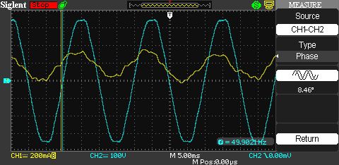
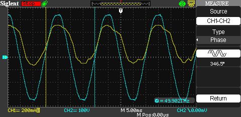
Finally, three more measurements of the power factor along with the current and voltage waveforms:
Bulb:
PF = 0.99
? = 8 °
Transformer soldering iron:
PF = 0.90
? = 346 ° (-14 °)
Drill with speed controller:
PF = 0.29
? = 348 ° (-12 °)
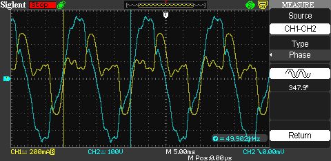
As you can see from the above screenshots, this is not an ordinary cos ?, but it looks like a reasonably correctly calculated Power Factor.
To sum up - both meters work properly and are successfully suitable for long-term monitoring of electricity consumption by a device or as a sub-meter. However, it must be taken into account that the device has not been tested by any reputable laboratory and has virtually no security. There is indeed an insulating slot between terminals L and N, and a VDR 10D471K varistor is connected in parallel to these terminals. However, there is no fuse that would blow after the varistor is tripped. Despite these imperfections, I have been successfully using such a meter built in an electrical switchboard for the third yearto monitor energy consumption by external receivers on the plot (hydrophore, pond, gate). The switchgear is located on the wall of the building and is not hermetic, and the meter has survived the second winter and works perfectly. You just have to remember that it is not a laboratory instrument and its indications should be treated as indicative.
I am also enclosing a user manual translated by me.
I received the above two power / energy meters for testing. They are identical in appearance, the only difference is the transformer attached to the stronger version. The dimensions of the module are 85x47 mm (part recessed into the housing), depth: 24 mm, the front panel dimensions are 90x55 mm, and the display 55x30 mm.
The weaker version (20 A / 4.4 kW) is equipped with a measuring shunt with a resistance of 3 m?, while the more powerful version (100 A / 22 kW) has an external current transformer with a ratio of 2000: 1 (or if you prefer 50 A / 25 mA) type DL-CT10CL. The transformer itself, according to the manufacturer, is adapted to measure the current with an intensity not exceeding 150 A. The power consumption of the meter is below 1 W. The meter is equipped with one button with which we can turn on or turn off the backlight, set the power overload alarm and reset the energy meter . The function is selected by holding the button for various times. However, there is no need to worry as the time differences are so long that the risk of accidentally erasing the energy meter is negligible. It is worth mentioning that the meter maintains its indications after disconnecting the power supply. However, it does not retain the screen backlight status - each time after a power failure, it starts with the backlight on.
In the box, in addition to the meter and, if necessary, a transformer, we find a modest instruction manual, printed on a sheet of (more or less) A6 size. There is an English version on one side of the page and a Chinese version on the other.


Both meters are based on the same PCB, differing only in the configuration of the resistors. In the 20 A version, these are two 6 m? resistors, size 2512, connected in parallel, forming the measuring shunt, and in the 100 A version (equipped with a transformer) it is a 1 ? resistor, size 0603. With a maximum current of 20 A, a voltage of 60 will be created on the shunt. mV, which will give 0.6 W per resistor (resistors of this size can dissipate 1 W). In the version with a transformer, at a maximum current of 100 A, a current of 50 mA will flow through the shunt, which will correspond to a voltage drop of 50 mV and a power of 2.5 mW, which the 0603 resistor should easily handle. The heart of the system is a specialized HT5019 microcontroller. It is a dedicated system for building single-phase power meters, based on the M0 kernel, with 128 KB of FLASH memory. The second chip present on the board (VK1621B) is the LCD driver (32x4). The electronics are powered by a primitive transformerless power supply, made of a capacitor and a resistor. There is no protection whatsoever for this power supply (not counting the resistor). I also suggest removing the board from the housing and cleaning it, because in both meters I found flux residues (mainly from the display side) and, what's worse, droplets of solder.
View after removing the back cover:


The connection of both modules is very simple - they are equipped with a solid screw connection, the two terminals of which, labeled L and N, are used to connect the power supply. In the 20 A version, the receiver is connected between the L terminal and the "1" terminal (the shunt is on the N wire). In the case of the version with a transformer (connected to terminals "1" and "2"), the direction of installing the transformer on the wire is important - there is an arrow on it, which should point in the direction of "zero" (L -> N). The opposite assumption will result in the lack of indications of active power and power factor.
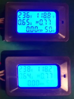
The workmanship of the meters is not overly solid, but the casing does not seem to fall apart in your hands. Unfortunately, it is impossible to talk about any water / dust resistance of this meter. The button, which is a micro-switch protruding through the hole in the housing (without any key / cover), also hurts a bit. Another issue is the lack of the CE mark ... it seems to be irrelevant, but without this mark, the product cannot be marketed in the EU. I do not know if it is a question of my copy, but the 20 A version has a clearly worse display - it has very small viewing angles, and after turning on the backlight it becomes practically unreadable. In the 100 A version (also my previously purchased copy) the display is perfectly legible, both without and with backlight:

The device does not have any certificates, and the manufacturer does not even specify the accuracy of the measurements. The resolution of the indications is as follows:
voltage: 1V
power: 0.01 W (below 100 W)
current: 0.01 A (below 10 A)
power factor: 0.01 (1%)
energy: 0.01 kWh (up to 1000 kWh)
frequency: 1 Hz
The values in parentheses are the limit of the lowest measuring range, higher values can be measured but with reduced resolution.
For the purposes of the tests, I improvised a measuring stand in which I connected both meters in series:
         _____________          _____________
         |           |          |           |
WE ======|   GB202   |====..====| P06S-100  |-----.
         |___________|    ||    |___________|     |
                          ||    _____________     |
                          ||    |           |     |
                          ''====|  P06S-20  |=====O===== WY
                                |___________|
As a reference, I used a GB202 type power meter and two multimeters (UT-139C for current measurement and AN8008 for voltage measurement).
The first test consisted of connecting a load in the form of a 40W bulb:
| P06S-20 | P06S-100 | GB202 | Multimeters | |
| U [V] | 238 | 236 | 236.4 | 237.0 |
| And [A] | 0.18 | 0.18 | 0.234 | 0.184 |
| P [W] | 43.27 | 43.35 | 43.6 | 43.68 |
| PF | 0.99 | 0.99 | 0.80 | - |
It might seem that the power factor readings basically disqualify my "reference" meter, but swapping the circuit so that the GB202 was connected last made the results agree:
BG202 (40 W bulb):
U = 234.3 V.
I = 0.179 A
P = 42.8 W.
PF = 1.00
Thus, in subsequent tests, the GB202 wattmeter was connected last:
               _____________
               |           |
WE ======..====| P06S-100  |-----.
         ||    |___________|     |
         ||    _____________     |     _____________
         ||    |           |     |     |           |
         ''====|  P06S-20  |=====O=====|   GB202   |==== WY
               |___________|           |___________|
Test no.2 (power supply 100 W load):
| P06S-20 | P06S-100 | GB202 | |
| U [V] | 238 | 236 | 236.3 |
| And [A] | 0.64 | 0.65 | 0.621 |
| P [W] | 118.2 | 118.8 | 118.3 |
| PF | 0.77 | 0.77 | 0.78 |
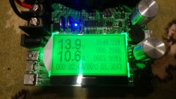
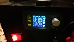
Another attempt was to be loaded with a laboratory power supply with a power of 0.5 kW, loaded with 150 W active load ... unfortunately it was supposed to be, because the artificial load gave up after several seconds of work under the maximum load.


Test no.3 (power supply 150 W load):
| P06S-20 | P06S-100 | GB202 | |
| U [V] | 237 | 236 | ? |
| And [A] | 0.95 | 0.97 | ? |
| P [W] | 179.6 | 180.8 | ? |
| PF | 0.79 | 0.79 | ? |
Before I could see the readings from GB202 - the transistor in the load was punctured.
Attempt no.4 (other power supply, load in the range 50-110 W):
| P06S-20 | P06S-100 | GB202 | |
| U [V] | 239 | 240 | 238.8 |
| And [A] | 0,35 | 0,35 | 0,338 |
| P [W] | 50,50 | 50,42 | 49,8 |
| PF | 0,60 | 0,60 | 0,6 |
| P06S-20 | P06S-100 | GB202 | |
| U [V] | 239 | 237 | 237,6 |
| I [A] | 0,51 | 0,51 | 0,503 |
| P [W] | 76,35 | 76,62 | 75,2 |
| PF | 0,63 | 0,63 | 0,63 |
| P06S-20 | P06S-100 | GB202 | |
| U [V] | 240 | 238 | 238,2 |
| I [A] | 0,68 | 0,69 | 0,659 |
| P [W] | 101,8 | 102,5 | 100,1 |
| PF | 0,62 | 0,62 | 0,63 |
| P06S-20 | P06S-100 | GB202 | |
| U [V] | 239 | 238 | 237,9 |
| I [A] | 0,74 | 0,75 | 0,72 |
| P [W] | 111,8 | 112,4 | 110,2 |
| PF | 0,62 | 0,62 | 0,61 |
Próba nr 5 (toster 1 kW):
| P06S-20 | P06S-100 | GB202 | |
| U [V] | 240 | 239 | 239.0 |
| And [A] | 4.21 | 4.27 | 4.150 |
| P [W] | 1.01 k | 1.02 k | 994.7 |
| PF | 0.99 | 0.99 | 0.98 |
Test no. 6 (2.4 kW kettle):
| P06S-20 | P06S-100 | GB202 | |
| U [V] | 235 | 234 | 233.6 |
| And [A] | 9.16 | 9.30 | 9,109 |
| P [W] | 2.14 k | 2.16 k | 2149 |
| PF | 0.99 | 0.99 | 0.99 |
As you can see, the devices differ slightly in terms of their indications, but as for the indicator, such discrepancies are acceptable.
Finally, three more measurements of the power factor along with the current and voltage waveforms:
Bulb:
PF = 0.99
? = 8 °

Transformer soldering iron:
PF = 0.90
? = 346 ° (-14 °)

Drill with speed controller:
PF = 0.29
? = 348 ° (-12 °)

As you can see from the above screenshots, this is not an ordinary cos ?, but it looks like a reasonably correctly calculated Power Factor.
To sum up - both meters work properly and are successfully suitable for long-term monitoring of electricity consumption by a device or as a sub-meter. However, it must be taken into account that the device has not been tested by any reputable laboratory and has virtually no security. There is indeed an insulating slot between terminals L and N, and a VDR 10D471K varistor is connected in parallel to these terminals. However, there is no fuse that would blow after the varistor is tripped. Despite these imperfections, I have been successfully using such a meter built in an electrical switchboard for the third yearto monitor energy consumption by external receivers on the plot (hydrophore, pond, gate). The switchgear is located on the wall of the building and is not hermetic, and the meter has survived the second winter and works perfectly. You just have to remember that it is not a laboratory instrument and its indications should be treated as indicative.
I am also enclosing a user manual translated by me.
Cool? Ranking DIY


