logo elektroda
logo elektroda
X
logo elektroda

ESP32 + TASMOTA + relay module - no response

008 1215 9
ADVERTISEMENT
Treść została przetłumaczona polish » english Zobacz oryginalną wersję tematu
  • #1 20857513
    008
    Level 7  

    As per topic. I'm trying to make a relay module on an ESP32 with TASMOTA software uploaded.

    I've tried various configurations but the relay doesn't respond to the state change signal. I hear a click when I connect the signal pin (brown cable), but when I click the switch from the web interface nothing happens.

    I have the signal pin connected to GPIO 26
    In the module connected to In1

    Red Vcc -> VIN
    Black Gnd -> Gnd

    In the Template tab in the TASMOTA settings GPIO26 is set to Relay. I also tried the settings Relay_and Relay_b as well as Relay_bi but it doesn't change anything.

    Anybody knows how to make this work and what the number means with the GPIO setting?

    The relay module was labeled for the Arduino but I hoped it didn't matter much but something feels like it won't work.
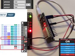
    ESP32 connected to a relay module and Tasmota interface .
    Do you have a problem with Arduino? Ask question. Visit our forum Arduino.
  • ADVERTISEMENT
  • #2 20857690
    urkotrebor
    Level 21  
    The ESP32 operates at 3.3V and these relays need 5V , another thing is that you probably broke the ESP32 because it was loaded with too much current .
    You need a circuit that will adjust the ESP output to the relay operating parameters .
    GPIO are the pin designations of the ESP connectors .
  • ADVERTISEMENT
  • #3 20857715
    008
    Level 7  

    How can the ESP32 run on 3.3 when it is powered from a USB port which is 5V? I've been using it with this power supply for 3 years and somehow it works.
  • ADVERTISEMENT
  • #5 20857775
    khoam
    Level 42  
    008 wrote:
    How can the ESP32 run on 3.3 when it is powered from a USB port which is 5V?
    There is a 3V3 stabiliser on the board with the ESP32. The ESP32 operates in 3V3 logic, not 5V.

    Added after 1 [minute]:


    008 wrote:
    The relay module was labeled for Arduino
    What model of relay module is this? How about a link?
  • #6 20857940
    xury
    Automation specialist
    The relays are on 5V. The question is what is the name of the pin from which the relay board is powered. There are different ones. In some where the red wire is plugged in there is an IN that goes through the diode to the stabiliser, and in some there is 5V which is directly connected to +5V from the USB.
  • ADVERTISEMENT
  • #7 20858650
    008
    Level 7  

    According to what is written on the ESP32 forum, if the board is supplied with 5V then that voltage should also be present on the VIN pin, which is the one I have connected the relay to. The status change signal reaches the board because the blue LED flashes when the MQTT transmission is active, but the relay does not respond - I do not hear a click. It only clicks when I connect the pin.

    https://esp32.com/viewtopic.php?t=11904

    Forum screenshot discussing ESP32 and 5V power supply. .
  • #8 20858699
    khoam
    Level 42  
    @008 Your best bet is to measure for yourself what the voltages are on the relay module's VCC supply and on one of its In inputs, to which the GPIO from the ESP32 is connected, when that GPIO is in the high state. The post you quoted is more of a storytelling nature and I don't think it is very helpful.
    Generally, the VIN on the ESP32-Devkit module is used to alternatively supply power to that module, instead of via USB.
  • #9 20858749
    008
    Level 7  

    Okay if I set the used pin 26 (D26) to Relay_i then on VIN and IN1 I have the following voltages:

    1.6V - if the virtual switch in the interface is in OFF state
    4.9V - if the virtual switch in the interface is in ON state

    The relay when the IN1 pin is connected clicks (closes) but there is no response when I try to turn it off.


    Screenshot showing GPIO pin configuration in the interface.

    User interface with ON button and additional configuration options.
    .
  • #10 21128794
    008
    Level 7  
    If anyone had a similar problem with this module, the problem is solved by connecting it to 3.3V instead of the 5V the vendor says it requires to work.

Topic summary

The discussion revolves around issues faced when connecting a relay module to an ESP32 using TASMOTA software. The user reports that the relay does not respond to commands from the web interface despite hearing a click when the signal pin is manually connected. Various configurations were attempted, including setting GPIO 26 to different relay modes. Responses highlight that the ESP32 operates at 3.3V while the relay requires 5V, suggesting potential voltage mismatches. Users recommend checking the voltage levels on the relay module's VCC and IN inputs during operation. A solution was proposed where connecting the relay to 3.3V instead of 5V resolved the issue.
Summary generated by the language model.
ADVERTISEMENT