Elektroda.com
Elektroda.com
X

MUSTOOL MDS8207 - multimeter with oscilloscope mode. First impressions.

zgierzman 21582 24
This content has been translated flag-pl » flag-en View the original version here.
  • MUSTOOL MDS8207 - multimeter with oscilloscope mode. First impressions.

    I received the pre-ordered (and therefore much cheaper) MUSTOOL MDS8207 multimeter with oscilloscope function.
    As of today, its price is quite high, PLN 385.49, but I paid PLN 286.41.

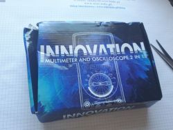
    The equipment came in a cardboard box packed in a bag with the Banggood logo.
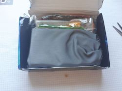
    The box was heavily damaged but the contents were intact. And the content is:
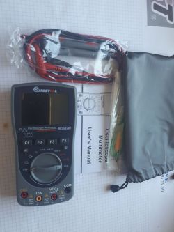
    Multimeter, test leads, K thermocouple and user manual. Plus a rag bag.

    MUSTOOL MDS8207 - multimeter with oscilloscope mode. First impressions. MUSTOOL MDS8207 - multimeter with oscilloscope mode. First impressions. MUSTOOL MDS8207 - multimeter with oscilloscope mode. First impressions. MUSTOOL MDS8207 - multimeter with oscilloscope mode. First impressions.

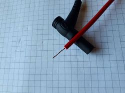
    The cables make a good first impression - soft, flexible, pleasant to the touch. But the circuit continuity test showed that "something in them is not making contact". The buzzer worked once, and once it didn't, once the resistance of the circuit was 2 ohms, in a moment several hundred ohms ...
    The banana plugs are rather crap, and there are a few hairs inside the insulation. Probably copper, because they do not stick to the magnet, and when scraped, they do not reveal aluminum ;-)
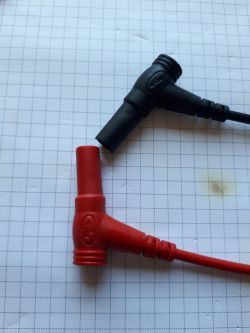
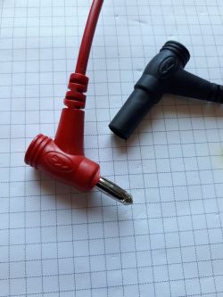
    MUSTOOL MDS8207 - multimeter with oscilloscope mode. First impressions. MUSTOOL MDS8207 - multimeter with oscilloscope mode. First impressions. MUSTOOL MDS8207 - multimeter with oscilloscope mode. First impressions.

    The housing of the multimeter is ordinary hard plastic, without any rubber elements.

    It's time to see how he measures:
    I focused on the oscilloscope function, because this is certainly what everyone is most interested in. I checked the traditional functions of the multimeter only briefly.

    As for this type of equipment, it starts up quite quickly, but refreshing the measurement result is annoyingly slow.


    The circuit continuity squeak works decently. Could be faster, but no drama. The probes came out blurry in the video, but you can get a general idea.


    The accuracy of voltage, current and resistance measurements is OK - but as I wrote: I did not take detailed notes. They certainly fall within the specification, which is not too high (1% - 2% depending on the value and range).
    Up to 100 measurements can be stored in the internal memory.
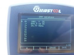
    MUSTOOL MDS8207 - multimeter with oscilloscope mode. First impressions.

    Oscilloscope:
    This feature lives up to its name more than its predecessor.
    https://www.elektroda.pl/rtvforum/viewtopic.php?p=18075818#18075818


    The user has basic functions at his disposal, almost like in a real oscilloscope.
    Sensitivity from 0.5V/div to 200V/div
    Time base from 12.5ns/div to 10s/div
    Trigger on rising or falling edge in Auto, Normal and Single modes.
    Of course, the trigger level can be adjusted as well as the shift of the graph.
    The manual states that you can manipulate cursors on a frozen graph (saved in Single mode). However, I couldn't turn it on, maybe it's the fault of the first, lame, firmware. Or am I doing something wrong...
    It is also possible to save up to 50 waveforms, but they can only be viewed on the built-in screen - there is no way to download them in any way.
    During observationThe basic measurements appear on the waveform, namely: peek to peek voltage, RMS voltage, average voltage and frequency.

    The first thing that caught my attention after connecting the generator was that the displayed frequency had nothing to do with the one from the generator. However, it turned out that changing the time base revealed the true course, but it's a big bug. If we do not know what to expect, we can be surprised - it is possible to get two stable waveforms on the screen for different time settings, and only one will be true...


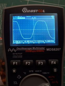
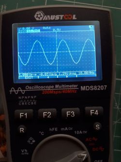
    Another problem, although I don't know if it can be avoided in this case, is the lack of compensation of the test leads. And while the sinusoidal waveform is imaged quite OK, the rectangle with steep edges has large overshoots. The manual mentions this and advises you to contact the manufacturer for a special shielded probe, but I put the topic aside for now ...


    The specification gives 40MHz and 200Ms/s bandwidth.
    Using the 3dB drop in amplitude method, I estimated that the real bandwidth for the sine is about 30MHz, maybe a little more. Maybe 35MHz. I did not measure when the amplitude will be exactly 0.707 of the input, I acted a bit "by eye". ;-)

    MUSTOOL MDS8207 - multimeter with oscilloscope mode. First impressions.

    I also wanted to check the calculation method based on the rise time, but I gave up here.
    I have a generator with a guaranteed rise time of 40ps, which for the Gaussian method should give me the ability to test hardware up to almost 9GHz ;-)
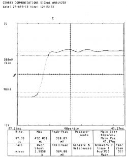
    MUSTOOL MDS8207 - multimeter with oscilloscope mode. First impressions.

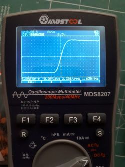
    BW = 0.35/trise
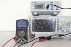
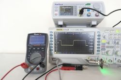
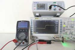
    The course and measurement on Rigol are shown in the photo. The measured trise is 2.3ns, which after substitution to the above formula gives over 150MHz
    MUSTOOL MDS8207 - multimeter with oscilloscope mode. First impressions. MUSTOOL MDS8207 - multimeter with oscilloscope mode. First impressions.

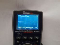
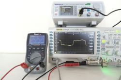
    However, connecting Mustool with its cables spoils the waveform itself, and the screen shows only ringing. Some kind of compensated probe would be necessary here.
    My first thought was an oscilloscope probe, but I abandoned that idea when I found in the manual that "Input resistance about 100Mom".
    MUSTOOL MDS8207 - multimeter with oscilloscope mode. First impressions.

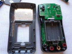
    Show me what you got inside...

    MUSTOOL MDS8207 - multimeter with oscilloscope mode. First impressions.

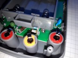
    No fuss here as well. Two boards soldered "on a sandwich" - and you can't see much without disassembling this equipment to pieces.
    There are two connectors - 8pin JTAG with described pins Vcc GND TDO TDI TMS TCK, and 4pin SWD.

    I am disgusted with the level of security. Here there is little (or maybe nothing) other than fuses, and the latter in the SMD version. CAT II 1000V and CAT III 600V are probably wishful thinking. And burning a fuse in the field is the end of measurements for a given day, because hardly anyone carries the equipment needed to solder a new one.
    MUSTOOL MDS8207 - multimeter with oscilloscope mode. First impressions.

    To sum up: this is not a device for everyone. And you certainly can't use this oscilloscope for serious measurements. However, as a handy device to quickly check "what's in the grass" it will be OK. Battery powered so you don't have to be overly carefuldo not short anything to ground, 700Vrms input voltage allows you to confidently manipulate mains voltages. If you could somehow compensate the frequency of the input circuit, it would be a really good device.

    Cool? Ranking DIY
    About Author
    zgierzman
    Level 31  
    Offline 
    zgierzman wrote 1660 posts with rating 1324, helped 95 times. Live in city Zgierz. Been with us since 2005 year.
  • #2
    szymon122
    Level 38  
    In my opinion, it is an interesting alternative to the DSO150. Despite the higher frequencies possible to measure, I chose the DSO150 because of the possibility of adding support for three digital channels.
    (I will write an article on how to do it in a few days)

    zgierzman wrote:
    it is possible to get two stable waveforms on the screen for different time attitudes, and only one will be true...

    So when measuring a signal with an unknown frequency, we don't know which one will be correct?

    zgierzman wrote:
    a rectangle with steep slopes has large overshoots

    Up to what frequency is a rectangle a rectangle?
  • #3
    TechEkspert
    Editor
    How do you estimate battery life?
  • #4
    tzok
    Moderator of Cars
    szymon122 wrote:
    So when measuring a signal with an unknown frequency, we don't know which one will be correct?
    Yes, this phenomenon is as old as DSO oscilloscopes and is called aliasing. It consists in "fitting" (hence the name) of sampling into points on successive periods of the measured waveform. We obtain an effect similar to that consciously used in the so-called. equivalent time sampling.
  • #5
    szymon122
    Level 38  
    tzok wrote:
    It consists in "fitting" (hence the name) of sampling into points on successive periods of the measured waveform

    So I understand that when measuring, for example, 10MHz, the meter will show both 10MHz and, for example, 5MHz? Is there any way to check which reading is correct?
  • #6
    Anonymous
    Level 1  
  • #7
    Fimek
    Level 15  
    Hi,

    Thanks for the review, the price is low, but so is the quality. For me, as a measuring instrument, it will not work.

    Do any of you have experience with another cheap multimeter-oscilloscope HANTEK 2D42, or another in this family?

    I am a bit tempted by this equipment, because the price is also low, but the quality seems to be OK.

    Regards,
    movie
  • #8
    zgierzman
    Level 31  
    szymon122 wrote:
    So when measuring a signal with an unknown frequency, we don't know which one will be correct?


    Look at this movie


    The wrong waveform (at the beginning of the video) is much less stable than the right waveform (at the end).

    szymon122 wrote:
    Up to what frequency is a rectangle a rectangle?


    As seen here:


    If at 1MHz a rectangle can still be recognized, then above 5MHz there is only ringing. The problem is that it lasts a certain time, so for low frequencies it is barely visible as a small peak at the beginning, and for higher frequencies it begins to dominate the signal.
    Another problem resulting from the resignation of the oscilloscope probe and the lack of compensation is the "boosting" of the sine for certain frequencies. This is also seen in one of the videos. The amplitude of the signal on the screen increases, although the amplitude of the input signal does not change.

    TechEkspert wrote:
    How do you estimate battery life?


    It's hard to say after one day ;-)
    The machine sucks, takes less than 140mA, regardless of the range, at 4.5VDC on the power supply. Assuming the capacity of the batteries / accumulators at 2000mAh, theoretically it will be about 15 hours of work.
    After turning it off by auto power off, about 1.6mA is still being drawn ... Lipa.

    grawastar1986 wrote:
    In such meters, I always wonder why such a low-quality display is installed there. It should be at least some oled. Judging by the photos, this display is not even suitable for an alarm clock ;)


    It's not a top-flight display, but there's no drama either. It has decent contrast and brightness, it can be used. The angles from which you can look at it are really OK. Only looking "from above" we will see the negative, but still readable.
    Interestingly, the display does not lose legibility as the supply voltage decreases. At 2.8VDC, the image is still sharp, although the backlight is no longer working.

    Close-up photo of the display

    MUSTOOL MDS8207 - multimeter with oscilloscope mode. First impressions.

    Fimek wrote:
    Thanks for the review, the price is low, but so is the quality.


    You get what you pay for. If you don't have a decent decent probe, you can't expect it to work nicely at higher frequencies. I also looked at this Hantek, but it is twice as expensive, and I usually need kHz at work, not MHz ...
  • #9
    krisRaba
    Level 31  
    It seems to me that the target is completely different, so they did not pay attention to some things. This is an interesting tool, for example, when servicing a car or running around the production hall, where a desktop oscilloscope is unwieldy. You can see the waveform from the sensor, whether it is stable or cluttered, etc. An ordinary multimeter will not show many things, it will display, for example, the averaged value or the calculated RMS of the waveform, and you wanted to check some PWM signal or ramps ...
    In such applications, it is kHz rather than MHz and such a tool may work. And if someone wants to analyze digital protocol frames, etc., then sorry.. ;-)
  • #10
    PawelSkrzypulec76
    Level 8  
    Soldered SMD fuses are really an embarrassment and a disgrace for the designer. In unfavorable conditions (high energy) they will evaporate together with the solder pads to which they are soldered.
  • #11
    zgierzman
    Level 31  
    Wow, a techie. ;-D

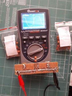
    MUSTOOL MDS8207 - multimeter with oscilloscope mode. First impressions.

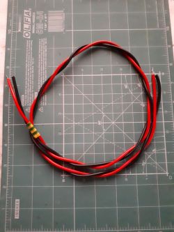
    I found a moment for fun and with the help of this prototype I disappeared the ringing at the rapidly rising slopes. ;-D

    MUSTOOL MDS8207 - multimeter with oscilloscope mode. First impressions. MUSTOOL MDS8207 - multimeter with oscilloscope mode. First impressions. MUSTOOL MDS8207 - multimeter with oscilloscope mode. First impressions.

    The real bandwidth is 10MHz - measured in two ways: rise time for a rectangular signal (anyone can count, I attach photos), and a decrease in the amplitude for a sine of 3dB.

    This is for the lowest range of input voltages. The multimeter has three such ranges, you can hear the relays clicking when switching. But for now I don't have the equipment to see what it looks like at higher input voltages...
  • #12
    Janusz_kk
    Level 37  
    So you gave 330pF parallel to the input of the meter?
  • #13
    zgierzman
    Level 31  
    Well, 320pF, but that's a detail. For the first attempt, I had soldered wires made in a "twisted pair" to this system. Originally I was going to connect them to the generator, then I used a different alligator clip cable. Then (both cables connected - the one with crocodile clips and the one soldered) the needed capacitance was lower, something about 290pF.

    MUSTOOL MDS8207 - multimeter with oscilloscope mode. First impressions.

    The type of wires, their length and arrangement are important.
    That's why I show it more as a curiosity, because you would have to select the capacitor for the wires individually.

    EDIT:

    Having a soldered BNC socket, I tested the connection of the generator and the multimeter with a coaxial cable. Then the capacitance needed was 100pF, and the bandwidth was about 14MHz.
  • #14
    maciej_333
    Level 38  
    Wouldn't it be better to connect a 1 M? resistor in parallel to the meter terminals and use a simple 1:10 passive oscilloscope probe? Additional capacitances may then be added if it is not possible to compensate for this.
  • #15
    zgierzman
    Level 31  
    maciej_333 wrote:
    Wouldn't it be better to connect a 1 M? resistor in parallel to the meter terminals and use a simple 1:10 passive oscilloscope probe? Additional capacitances may then be added if it is not possible to compensate for this.


    Well, I don't know... With a 1:10 divider, measuring small voltages would probably be impossible. From 0.5V/div it would become 5V/div, which would limit the application. But already in industry, where the control voltage is usually 24V, maybe it would work. I'll think about it and maybe check this idea out. ;-) But somehow this idea doesn't appeal to me, I don't know why.

    EDIT:
    As a rule: it works.

    MUSTOOL MDS8207 - multimeter with oscilloscope mode. First impressions.

    Maybe even improved band, about 12.5Mhz
    But if I'm going to install some inventions, I'd rather solder a properly selected capacitor to the inside of the multimeter than wear a 1:10 probe and an adapter.
  • #16
    TechEkspert
    Editor
    Perhaps in the next version there will be a separate BNC connector for DSO mode and an appropriate input circuit adapted to a typical 1:10 probe?
  • #17
    ptero
    Level 23  
    It's a good thing, though, that I didn't pre-purchase this meter. I will wait for version 3 :) maybe it will be better developed. It was supposed to be much better - it turned out as always :) Although at lower frequencies it's not bad, but it's not that...
  • #18
    ADAM Fx
    Level 12  
    I checked the multimeter first.
    I told about my feelings in the video https://youtu.be/aWud3uwYIe4
    I also added a link in the description to this topic because the article is really very good.
    In general, I wanted to refer to the defect found, namely the inability to move the stopped waveform.

    I checked it at home in a multimeter that was no longer purchased in advance (Price 69.99 with a coupon) and there is still no CURS option under F4.

    I also found one more problem, namely the lack of the POS option for measuring with cursors.

    And the error in the instructions to turn off auto off you need to hold down F1 when turning on, not R. And to turn on silent mode F4.

    I have notified the manufacturer and here is the response.

    Manufacturer's response (translation) regarding the inaccuracies I found:


    1. After entering TIME mode, there is no POS option and related functions under the F4 button

    Answer: under the F1 button, not F4. The first series of goods has no function with it, and the second series does.


    2. After stopping the waveform (HOLD or Single) under Kalisz F4 there is no CURS and related functions. (the F4 button works because it makes a sound but the option is invisible and does not respond)

    Answer: The first batch of goods does not have CURS, TIME and POS functions. In the future it will


    3. there is an error in the manual, the "AUTO OFF" function is turned off without holding R and F1 and I did not find a mention of mute and the mute option is under F4

    Answer: The manufacturer was also aware of this problem. Will improve it. Mute Mode: Enabled by pressing and holding the F4 button to select Mute Mode, but Mute Mode does not show any prompts with symbols on the LCD screen. The information in the manual will also be improved in the future.

    Regards!
  • #20
    Spryciarz19933
    Level 5  
    So is it worth it or not?
  • #21
    zgierzman
    Level 31  
    Spryciarz19933 wrote:
    So is it worth it or not?


    You have to evaluate yourself. You have descriptions, think about what you need it for, because there is no universal answer.

    Put yourself in the shoes of a farmer who has to plow a field to the very horizon. He has 200,000 in his pocket and needs to buy something.
    Is it worth buying an Audi A6?

    Same with this invention. One will use it every day and will be satisfied, and someone else will consider money thrown away.
  • #22
    krisRaba
    Level 31  
    zgierzman wrote:

    Put yourself in the shoes of a farmer who has to plow a field to the very horizon. He has 200,000 in his pocket and needs to buy something.
    Is it worth buying an Audi A6?

    I really liked your example :-D On point
  • #23
    ADAM Fx
    Level 12  
    Spryciarz19933 wrote:
    So is it worth it or not?

    I use it often and I'm satisfied - very helpful in my hobby. most recent examples:


    But I confirm
    zgierzman wrote:
    You have to evaluate yourself
    - see what people use for and whether it meets your needs.

    Ps. Don't buy the Audi A6;/ it's not as good as the Audi 80 B3 / B4 ;)
  • #24
    pawel_x
    Level 13  
    You need to know exactly what you want to measure.
  • #25
    SlaWasII
    Level 12  
    zgierzman wrote:

    As for this type of equipment, it starts up quite quickly, but refreshing the measurement result is annoyingly slow.


    What you showed in this video is not the time to refresh the result!
    This is the time for the multimeter to select the measuring range in AUTO mode. Set the measuring range manually and then you will see that there are 2.5 measurements per second. Do you need faster?! Unless to get nystagmus... ;)

    Also, thanks to Zgierzman for the review. The speck flew.