logo elektroda
logo elektroda
X
logo elektroda

T.amp TSA 4-1300 Power Amplifier Issue: Not Turning On, Red Diode Flashing, No Visible Damage

Matek920605 70464 346
ADVERTISEMENT
Treść została przetłumaczona polish » english Zobacz oryginalną wersję tematu
  • #241 19918466
    Ziemowit1973
    Level 13  
    aaanteka wrote:
    It was already ...

    ---
    Thanks for your interest in my question - I thought I wouldn't find out :)
    So yes - I have 2.5 kW transformers for free - I will give myself two in parallel !!!
    Kondy 6800 uF 63 V which will easily go to 70V I also have for free and I have a lot of them !!!
    ---
    I'm an electronics engineer, but I still have to learn a lot
    Those who know this design, tell me if my idea is worth implementing.
    The amplifier is to operate only in the 4x xxxxxxx Watt configuration - no bridges.
    ---
    how do I do this power supply, it will be trouble-free ??? Say because I don't want to work and load money.
    The amplifier is supposed to be made in the club - no wear - I will put it under the table and it's cool.
    ---
    If it is worth doing it, I would ask you to advise what capacitances to give at all voltages - I have a lot of capacitors.
    \ greetings and thanks for your interest :) !!!
  • ADVERTISEMENT
  • #242 19918698
    aaanteka
    Level 42  
    Ziemowit1973 wrote:
    So yes - I have 2.5 kW transformers for free - I will give myself two in parallel !!!
    What such? Where can you fit two such transformers? In addition, these transformers, which you have, do not have 6 secondary windings with appropriate output voltages.
    Ziemowit1973 wrote:
    I'm an electronics engineer, but I still have to learn a lot
    Those who know this design, tell me if my idea is worth implementing.
    The amplifier is to operate only in the 4x xxxxxxx Watt configuration - no bridges.
    Have you read the topic from the beginning, only the last few posts? In the subject, you have quite well presented disadvantages of this design, among others by me ;) . Briefly and vividly speaking: - an incorrectly made construction at every stage in the "Fiat 126p" type cannot be improved and made a construction tailored to the "Mercedes" or "Ferrari" of stage amplifiers.


    Ziemowit1973 wrote:
    what capacities to give at all voltages - I have a lot of capacitors.
    It doesn't work that way, many, different, whatever.
  • #243 19923377
    Ziemowit1973
    Level 13  
    anteka thanks, I read it twice.
    From what I can see, it is not fully explained what is defective - power supply or terminals :(
    If the ends themselves were ok, it would be worth making a separate, failure-free power supply.
    ---
    I bought two tips and started repairing :)
    I will describe what and how when I manage to repair.
  • #244 20020227
    Robercikxxx
    Level 15  
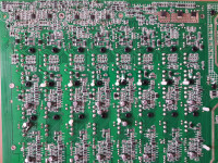
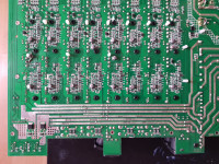
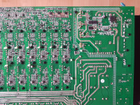
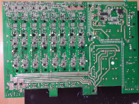
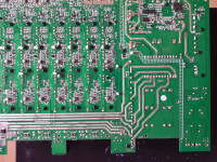
    It is not really known what is defective, whether the tip itself or the power supply. I personally have five of these amplifiers and, as someone wrote earlier, there are three versions of it. The first version differs from the others that the manufacturer did not make the finished product, but wanted to sell it. Therefore, it did not give a 15V zener diode and a resistor on the gates of the power bridges to ground. And probably later they were added to websites. Another difference is that the + 15V, -15V auxiliary power supply is taken from the + 60V, -60V terminal voltage. And only in later versions, the auxiliary power was taken from the + 30V, -30V tap. The + 30V disconnect in the first version was also used, but it was only used to power the + 24V stabilizer. But maybe a little bit about my copies. In the first copy of the latest version, only the power supply was damaged. So transistors, gate resistor, zener diodes next to transistors, driver. In the second copy of the latest version, one end and the power supply were damaged. So, final transistors and a power supply. So what was damaged in the first piece in the power supply. In the next amplifier, i.e. already in the third version, but it was the first version, the power supply was damaged and I have something else with the fan system because when I turn it on without a signal and wait a few minutes, the fans themselves increase the speed to the maximum. Although the heat sink of the power supply terminals and transistors are cold, of course the bridge and triac heat sink is also cold. In addition, sometimes it is so that the terminal goes into some error at half of the input signal and turns off the output relays. But only on one channel this happens. On the other three, I can increase the sound to the maximum and nothing turns off. So I did not finish this tip. I haven't fixed the next pieces yet. So sometimes the power supply is damaged and when the end is damaged, it drags the power supply with it because there is no protection for exceeding too high output current in this end. I am giving you some pictures of the first version of the power amplifier board.
  • ADVERTISEMENT
  • #245 20020442
    Ziemowit1973
    Level 13  
    Robercikxxx wrote:
    there are three versions of it

    In one version I have 100 uF 25V electrolytes connected to ir2110 one electrolyte for one system, bootstrap in this version 3x1uF
    ---
    Do you have a cheap source of 4 transistors for a power supply ??? maybe some replacement for 200 amps ???
    Digging through Farnell, I find something there - but will it work?
    SGL160N60UFDTU
    IGZ100N65H5XKSA1
    FGH75T65SQDT-F155
    IKQ100N60TXKSA1
    ---
    DG100X07T2 - IGBT, 200 A, 1.45 V, 1.071 kW, 650 V, TO-247 Plus
    the one above is probably impossible to burn anymore :)
    Everything is expensive
    ---
    Curiosities - this is what I found with Farnell
    IRGP4066DPBF ---- IGBT, 75 A. , 1.7V, 454W, 600V, TO-247AC
    IRGP4066D-EPBF - IGBT, 140 A. , 1.7V, 454W, 600V, TO-247AD
    This is number 75A and 140A !!!
    Krzyk2 wrote:
    the rest of the transistor, i.e. IRGP4066D-EPBF, is important and it was used in the longest-lived version

    Krzyk2 - what you write would be correct :)
    ---
    I greet everyone :)
  • #246 20020898
    Robercikxxx
    Level 15  
    I used the IRFP460 to start the power supply, and only when everything was ok, I took out the IRFP460 and soldered the target transistors. It is worth giving fuses for powering transistors, i.e. power supply from the network after bridges and after capacitors. At + 310V. That is, cut the path and solder the fuse on one pair and also on the other. The fuses saved me twice from burning the transistors in the power supply. I assumed 3.15A 250V, two pieces.
  • #247 20021396
    aaanteka
    Level 42  
    Gentlemen, I will ask for the rut:
    - what is the purpose of trying to repair something that has been incorrectly constructed without the knowledge of the functioning of individual elements, and not thoughtfully packed into the housing?
    It has already been mentioned in response that it is for cognitive and learning purposes, but in this way you will learn nothing except spending money, wasting time and damaging elements in a faulty design. Sisyphean work, nothing more.

    Added after 3 [minutes]:

    Ziemowit1973 wrote:
    Curiosities - this is what I found with Farnell
    IRGP4066DPBF ---- IGBT, 75A, 1.7V, 454W, 600V, TO-247AC
    IRGP4066D-EPBF - IGBT, 140A, 1.7V, 454W, 600V, TO-247AD
    This is number 75A and 140A !!!
    What is my colleague so surprising about these individually selected parameters, let's add the currently average transistors?
  • #248 20021406
    398216 Usunięty
    Level 43  
    aaanteka wrote:
    Why try to fix something that has been incorrectly constructed without knowledge of the functioning of individual elements, and not thoughtfully packed into the housing?


    Sorry to cut myself between vodka and an appetizer, but I think the only reason I persist in trying to fix something like this is to prove to myself that I can.
    Nobody sees the point, except those who try. Maybe only after some time we will get confirmation that it is not worth it, that it does not make sense. that it is impossible to make g .. whip. So much and so much.
    In any case, I am waiting for such a final.
  • #249 20022098
    Robercikxxx
    Level 15  
    As you wrote, it may not pay off to repair these tips, but for those who are trying to repair them. They repair them for themselves, for their conviction that they can repair such an amplifier. They don't repair these tips for your money, but for theirs. So if you can and know how to help, help. Because once in a row I read your regrets that why do it, it does not pay off and stuff. So I would ask if you have to write like that and just discourage, don't write at all. As far as I know, this is a forum for people who need help, not for people who need your discouragement.
  • ADVERTISEMENT
  • #250 20022432
    398216 Usunięty
    Level 43  
    Robercikxxx wrote:
    They don't repair these tips for your money, but for theirs.
    A very correct point. I have no conscience to persuade anyone to throw money on a utopian project. You have to mature to find out what is profitable and what is not and why. Personally, I don't see the point in resuscitating the corpse, because Frankenstein will only come out of it - something that, even if it works, it is unstable, with no guarantee when it dies.
  • #251 20022518
    aaanteka
    Level 42  
    Robercikxxx wrote:
    So I would ask if you have to write like that and just discourage, don't write at all.
    But why are you painfully trying to deprive other experienced forum users of the fundamental right of this and similar forums to express their opinion on certain topics? My friend, we are dealing here with a typical amalgamation of a few amateur solutions thrown into one "crucible", proudly named by the Chinese producer as a stage amplifier and, until recently, with the branded logo of the German distributor.
    You want a miracle solution that technically, scientifically, does not exist.
    The only sensible solution would be to design and build this amplifier from scratch, add DSP, power distribution control system, add appropriate limiters, etc., because there is no other method of improving this bubula.
    The listed errors disqualifying this supposed product have been mentioned by me several times.
    Let me remind you of these essential aspects for a big "NO":
    It is impossible to improve and lead to failure-free operation of a poorly designed device, poorly made PCB circuit, poorly made mechanical arrangement of elements in the housing.
    In a word, the correct operation of the structure has the same chance of success as a bag of electronic components used in it, thrown into a bucket and flooded with molten tin. I think that everyone can now without illusions answer the question whether it is worth wasting time, time that will never come back for such inventions. It is not better to use it for learning, training in electronics, or other useful matters.
    Another issue is the unfair behavior of companies that dispose of this equipment from Europe - instead of properly disposing of the equipment for what they received money, they try to push into unaware amateurs on various auction sites as used equipment, not repaired, supposedly bearing the hallmarks of the efficiency of valuable equipment with theoretically overstated price of real stage equipment with real comparable parameters. As you can see, many have caught on to this type of strategy-like an offer.
  • #252 20032776
    Robercikxxx
    Level 15  
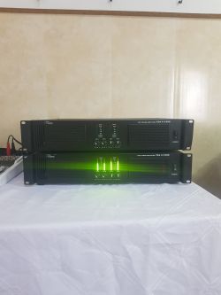
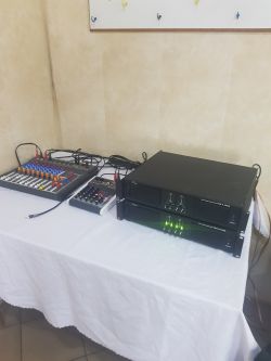
    The first event at this end was completed. A hall of 15 meters by 20 meters and I am happy with this end. I also talked to a friend who turned out to have this ending from the news and also says that he is happy. Of course, he said the same as I would say "everything will work using the equipment with common sense" T.amp TSA 4-1300 Power Amplifier Issue: Not Turning On, Red Diode Flashing, No Visible Damage T.amp TSA 4-1300 Power Amplifier Issue: Not Turning On, Red Diode Flashing, No Visible Damage
  • #253 20032841
    aaanteka
    Level 42  
    And when I deal with this equipment in a real stage application with dozens of copies, I can only say what I had before:
    - fatal, emergency, unfinished solution in no way suitable for a serious, professional sound system. I am writing this on the basis of the operation of a nationwide network of discos, which someone accidentally pressed them on. Repeated amplifiers working on crosovers, limiters with powers below the nominal power, could unexpectedly fail. An embarrassing failure rate in connection with the design errors that are already mentioned many times here. There was not a week without a breakdown, anyway, the problem ended in a legal way and the distributor and the manufacturer, despite the expiry of the warranty period, fully refunded the costs and amicably compensated. Interesting why? How and I wonder why the company officially withdrew from this model and accepted most of the amplifiers for a refund with a full refund of the purchase price?

    Currently, someone sells this equipment on auction portals to "incorrect optimists" in the style of you and your friends.
    The interchangeably used mid-priced stage amplifiers survived many premises and its operation, working flawlessly for several years.


    I will repeat the last time:
    - who needs a 4-channel amplifier as a compact solution, when you always need to have another efficient amplifier or two real two-channel amplifiers with you?
    That is why no sensible person from the sound and electronic market will recommend and approve of such an emergency and underdeveloped structure.


    Robercikxxx wrote:
    A room of 15 meters by 20 meters and I am happy with this end.
    This is not a test and some kind of enigmatic challenge, because this type of room with a height of 10-12m can be successfully amplified with an effective professional sound system with much lower power than that declared by this amplifier. To be precise, 2x 350W in an active PA system, and not at nominal power.

    But these are generalities that do not reflect the electronic aspect of this application, because nothing is known about:
    - method of use,
    - output power,
    - working time,
    -type of load,
    -type of purpose of the sound system (type of music, disco, techno, dance music, prayer meeting, training, wedding ...).
    It would be different if you said I served the 1000 people open air with a rock band performance, I powered the subwoofers with it.
  • #254 20032884
    2konrafal1993
    Level 38  
    aaanteka wrote:
    Currently, someone sells this equipment on auction portals to "incorrect optimists" in the style of you and your friends.
    While browsing the allegro, I found these miracles a long time ago, someone had and has a lot of them, I think that maybe I could buy and fix it, but it's worth finding out what's inside. It took me 10 minutes to read the forum where someone struggled with it and I said that it was a crap and not the equipment, there were many times "no parts, everything supposed to be functional and the transistors are burning, some unusual diodes, the equipment works but after a while it smoke again" there is a piece of PLN 350, but it should really cost PLN 100 because, apart from the housing, you can not use much of it. If someone is going to buy it, it is better to buy flowers for your mother or girlfriend for this money, there will be more benefits from it.
  • #255 20032921
    aaanteka
    Level 42  
    When the company utilized it in Europe, they initially paid (extra) 20 euros for the disposal of art, but there were no applicants. Then the amount was doubled. But as you can see, in Poland there are many people willing to pay for it, living in illusions.
  • #256 20210106
    monika2027_n7
    Level 10  
    check the voltage stabilizer 78m24 and whether there is voltage to it.

    Added after 2 [minutes]:

    The triac powers the bridges and the small converter powers the PWM driver and IGBT gate drivers

    Added after 3 [minutes]:

    replace also lm339 and lm555 correspond with delayed switching on of the inverter
  • #257 20448871
    xavlaur
    Level 1  
    For Thomann T.amp TSA 4-700 which are auxiliary voltages? I want to replace my switching supply (burned) by a transformer based one due mine is far too damaged.

    Also, I wonder if stabilisers (± 15 V by example) are on power supply PCB (I think so) or on final stage?
  • #258 20467394
    Robercikxxx
    Level 15  
    Unfortunately, I can't help you. Unless you send the power supply, I can fix it and then you'll know everything. I repair tsa 4 -1300 so I can tell you a lot about them. And I managed to repair the tsa 4-300 but I only have one piece.
  • #259 20522492
    Ziemowit1973
    Level 13  
    Hello
    The hair is on the head!!!
    T.amp tsa 4x1300
    - - -
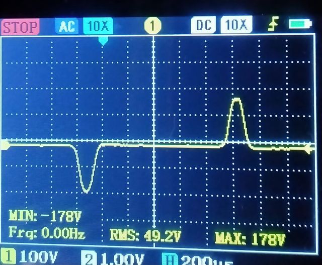
    I made measurements with a "sine wave" with a CF of about 11dB - that is, a waveform with such filling as the average musical material :)
    Load 8.7 ohms.
    The output voltage came out - 178V MAX, 49.2V RMS
    Power respectively - 3640W MAX peaks, (current 20 amps peaks)
    280W RMS power (current 5.6 amps average)
    I will not play a normal sine wave on this amplifier - I'm afraid.
    I will not do the test on a 4 ohm load either, because it is also a risk and looking at the above results, I do not even try to think how much will come out at the top.
    - - -
    As for how the clip works
    Interesting things happen here.
    When I reach 178V (then I have the knob on about 70%) and I keep turning the knob to increase the power:
    1 - the amplifier no longer boosts the power and it is impossible to get the flattening of the sine peaks characteristic of the clip - it looks as if the amplifier had " limits " or " peak reduction " which mutes the signal in such a way that clipping does not occur.
    2 - the sine wave is clean all the time without flattening at the top despite increasing the volume.
    3 - the CLIP LED on the front panel does not light up despite increasing the volume !!!
    4 - while the diode inside the board starts flashing informing me that " limits " or " peak reduction " It lowers my signal so that I don't clip it sometimes. - I will lead these diodes outside so that I can see them :) Too bad the manufacturer didn't.
    - - -
    I thought that the amplifier would calmly handle my parties only:
    I will convert the subs from 4 ohms to 16 ohms and then I am sure that I will not burn anything and the power in the peaks will be around 1800 watts, which is enough since the subs have a 1200 watt power program.
    - - -


    Gentlemen, thank you all for your help :)

    Without you, I would never have repaired this amplifier :)

    I bow my head!

    T.amp TSA 4-1300 Power Amplifier Issue: Not Turning On, Red Diode Flashing, No Visible Damage
    - - -
    Below is the sound for testing amplifiers :)
  • #260 20524041
    aaanteka
    Level 42  
    Ziemowit1973 wrote:
    Power respectively - 3640W max peaks, (current 20 amps in peaks)
    For such parameters, the final transistors would certainly be damaged. The measurement result is erroneous with a very large error. Probably the load changed parameters during the measurement. What was the actual burden?
    We measure the rated power according to assigned standards, not according to our "ideas".
    Ziemowit1973 wrote:
    I thought that the amplifier would calmly handle my parties only:
    I will convert the subs from 4 ohms to 16 ohms and then I am sure that I will not burn anything and the power in the peaks will be around 1800 watts, which is enough since the subs have a 1200 watt power program.
    Incorrect reasoning that differs from the actual parameters of this amplifier based on the applicable laws of physics for a real device of this type ( class AB amplifier ). And you probably misspoke, due to this and not another amplifier, we may be talking about one party here. ;) Although with the planned output power of 100W per channel, there is little chance of this invention working longer until the first failure.
    Well, some are irreformable and do not listen to others with more professional experience.
  • ADVERTISEMENT
  • #261 20524150
    Ziemowit1973
    Level 13  
    aaanteka wrote:
    What was the actual burden?

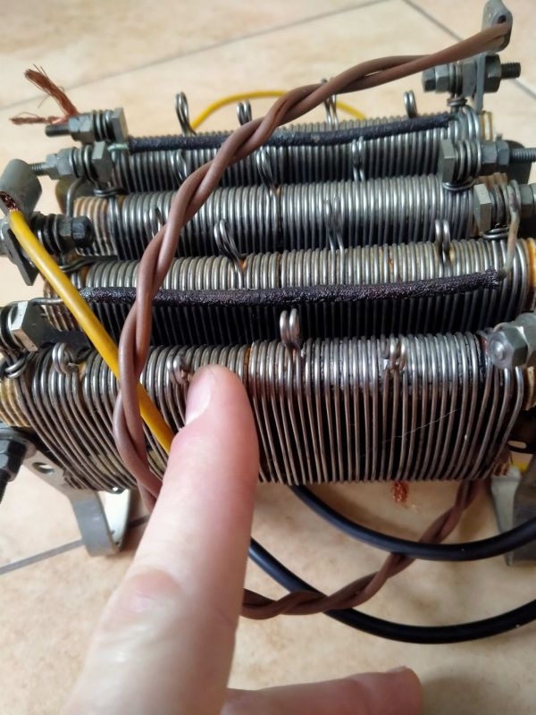
    The load was such a resistor as in the photo.
    ---
    It may sound amateur - how to measure the power of the amplifier? I can't input a normal sine wave!
    What am I doing wrong there? after all, you can see on the graph that in peaks for a fraction of a second I have 178V, from ohm's law I have 178V x 178V / 8.7 Ohms = 3642 Watts
    I emphasize 3642 Watt occurs only for a fraction of a second, which is the power of PMPO !!!
    Thanks for the post Aaantek :)

    T.amp TSA 4-1300 Power Amplifier Issue: Not Turning On, Red Diode Flashing, No Visible Damage
  • #262 20524429
    2konrafal1993
    Level 38  
    Ziemowit1973 wrote:
    I can't input a normal sine wave!
    Why? Sorry, I'm off topic. After all, it is a full-range amplifier, as far as I remember, there is some irs that has an integrator at the input, because without it you will not give the irs audio signal to the input. The integrator converts the audio signal into pulses with variable duty cycle and the SZ is connected to it. Unless it's done differently here. Explain what you mean.

    The power measurement is made with a sine of 1KHz and that would be enough of the parameters you need to provide to the amplifier.
  • #263 20524580
    aaanteka
    Level 42  
    aaanteka wrote:
    based on the applicable laws of physics for a real device of this type (class AB amplifier).

    >>18433299
    The amplifier is a solution of a 4-channel class AB amplifier with three supply voltages (3H). The power supply is made as a converter.
  • #264 20524649
    2konrafal1993
    Level 38  
    aaanteka wrote:
    The amplifier is a solution of a 4-channel class AB amplifier with three supply voltages (3H). The power supply is made as a converter.
    Then I was wrong that it is class D. Only I still do not know why the 1KHz sine measurement would be dangerous according to Ziemowit1973.
  • #265 20524705
    aaanteka
    Level 42  
    No one knows, some strange theory contradicting the functioning of acoustic amplifiers and the standards assigned to the measurement of acoustic power.
    In addition, a strange load value and inductive resistors.
  • #266 20552751
    Robercikxxx
    Level 15  
    >>20448871
    The power supply has auxiliary power supply +/- 15V and +24V main power supply is +/- 50V, +/-100V

    Added after 11 [hours] 53 [minutes]:

    The answer concerns the question about the TSA4-700 tip
  • #267 20602089
    roberrt
    Level 11  
    Hello
    I just have a TSA 4-1300 in repair.
    After repairing the power supply (IGBT, IR2110, diodes, etc.) and the second channel, the amplifier starts. Unfortunately, the voltage is too low to control the relays (about 13V) and only one turns on.
    78m24 that powers them is operational, but has only 15V at the input. The voltage from the transformer after resistors R462 and R463 and diodes D194 and D196 is 15.5V. Voltage before rectification on the transformer ~100V, single leg of the transformer to ground ~50V.
    Maybe some of you have had a similar experience and can help. Unfortunately, without a schematic, it's hard to understand the entire branch.
    Regards
  • #268 20604057
    Ziemowit1973
    Level 13  
    In the middle there are smd diodes that rectify the voltage of about 30V - there measure whether you have about 30V. The diodes are connected to the first double windings of the transformer :) Good luck.
    Check if you have other supply voltages - are you sure both halves of the converter are working - if one half of the converter will not work then you can hear the converter beeping and then all the voltages are cut by half but the amplifier surprisingly plays :)
  • #269 20607530
    roberrt
    Level 11  
    In fact, only half of the inverter worked (it didn't make any sounds for me). After replacing the faulty IR2110S, the voltages doubled. The auxiliary voltage supplying, among others, the 24v regulator is now 31.5v and everything works.
    Thanks for the help.
  • #270 20627975
    INtRO_Tech
    Level 14  
    Hello and welcome!

    Post described very generally, only for entertainment and educational purposes!

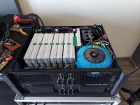
    I have had this electronic waste for a long time, so I decided to do something about it, and this freak was born:

    TSA 4-1300 converted into a transformer with 4 channels covered, working "H" keying and the largest possible toroid mounted.

    I removed the PCB section from the converter, in its place a base for a toroidal transformer was inserted.

    The transformer I had had 2x 15V and 2x 84V secondary windings, I additionally added 2x42V, so the main voltages are:

    P0: 2x21V DC
    H1: 2x59V DC
    H2: 2x118V DC
    H3: connected to H2

    The whole, after previous modifications, fit in the original housing and works properly.

    Before the final modification, I tested the power amplifier on many transformers, from 2x15V+2x24V, a few others to the current one. As for the operating points of the transistors - I did not touch anything here.

    The temperature thresholds work properly, surprisingly, the VU indicator on the front scales nicely with the power obtained from the input voltage, so no modifications were made here either, I checked the waveforms with the sine wave on the oscilloscope, regardless of the power supply voltage used - CLIP also reacted correctly.

    [!] IMPORTANT:
    This power amplifier, in addition to a poorly selected power supply and a few nuances, has a design flaw in the form of using the housing to connect ground points on the motherboard.

    This is not an exception, because such solutions are found in many devices, but when using a poor quality housing and poor threaded bushings, it is asking for trouble.

    The screws break the connection, the whole works mechanically to a small extent when moving, placing sideways or a bad grip for lifting, and this is enough to strain the connection.

    I would recommend connecting these points with wires after each repaired piece, otherwise disconnecting them, e.g. during transport, may cause damage again.

    MEASUREMENT AND OPERATION:
    Single channel, 50Hz sine per input, 4ohm resistor in water = 69.43V RMS on oscilloscope (69 * 69 /4R = ~1190W)

    I checked all channels on the above load "under CLIP", after 20 minutes of testing for each channel. Cooling responds properly on all channels.

    The bridge mode works properly, it has a decent kick but I did not measure the power due to the lack of an 8ohm resistor.

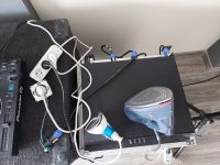
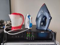
    I checked both bridges in the form of entertainment by connecting the SPEAKON-Extension adapter, plugging in various home devices. The power supply from the power amplifier output was correct, the ironing was successful and the coffee was brewed.

    In general, the whole thing works fine, I haven't installed the soft-start for the toroid yet, so sometimes it throws B16.

    The power stages are repeatedly overloaded, intentionally tortured and somehow the device lives.

    I think that in this configuration at lower power "it" should work without failure.

    Educational project for people who have in their collections some reasonably suitable goes to this amplifier, absolutely not economical when ordering a new transformer.

    With two loaded bridges, connecting 2x Polaudio TP118 18LW2400 8ohm basses and playing very hard after an hour, the transformers are warm.

    My project requires cosmetic corrections and additionally I would add some capacitors in the power branch.

    Regards!

Topic summary

The T.amp TSA 4-1300 power amplifier exhibits a failure to power on, with a flashing red diode near the capacitors and no visible physical damage. Investigation revealed multiple damaged IRGP4066D IGBT transistors on the primary side inverter, along with damaged power transistors (NJW0302GC), MOSFETs (GP105N15M), rectifier bridges (GBJ3006SF, 2506SF), and driver ICs (IR2110S, SG3525A). The amplifier uses a full-bridge power supply topology operating around 85-100 kHz with multiple symmetrical voltage rails (+/-15V, +/-40V, +/-60V, +/-90V, +/-160V) for preamplifier and power amplifier stages. The power supply design lacks galvanic isolation, current limiting, and effective overload protection, leading to frequent IGBT and associated component failures. SMD components such as EF8 and T4/H5 diodes (likely Schottky and Zener types) near the inverter and driver circuits are critical and often damaged. The triac (BTA41-600B) controlling AC mains to the rectifier bridge is also a common failure point. Repair attempts require replacing IGBTs, driver ICs, rectifiers, and passive components, but without a schematic or service manual, troubleshooting is challenging. Oscilloscope measurements of PWM signals and gate drive waveforms are essential for diagnosing dead time and control issues. Some users suggest replacing the entire power supply with a custom design due to the amplifier’s complex and failure-prone power stage. The amplifier chassis serves as a ground connection, which must be properly connected during bench testing. Auxiliary power supplies (e.g., 2x12V AC transformers) are used to test amplifier channels independently. Despite extensive repairs, issues such as persistent fault LEDs, relay non-activation, and channel-specific transistor failures remain common. The amplifier is considered difficult to service due to integrated power and control boards, lack of documentation, and complex SMD circuitry. The original design is reportedly based on the Chinese Leicozic DP41200 amplifier. Community consensus highlights the need for careful component verification, replacement of damaged SMD diodes and resistors, and cautious startup procedures using current-limited power supplies or light bulbs to prevent repeated damage.
Summary generated by the language model.
ADVERTISEMENT