FAQ
TL;DR: On ESP8266 + WS2813, a 20 A 5 V setup can still glitch the first LED; "WS2813 should be operated with 5V logic." Use a unidirectional level shifter, drive DI only, and ignore any clock pin. [Elektroda, marcingebus, post #18511388]
Why it matters: This FAQ helps ESP8266 makers fix first-LED misbehavior, wiring, and logic-level issues on WS2813 strips.
Quick Facts
- WS2813 uses a single data line; there is no clock line on the strip. [Elektroda, OliJot86, post #18511427]
- High-level threshold is approx. 4 V at 5 V supply, so 3.3 V is marginal. [Elektroda, ekrzychoooo, post #18526173]
- Real-world build: 5 m WS2813 powered from a 5 V/20 A supply. [Elektroda, marcingebus, post #18511388]
- Unidirectional 3.3 V → 5 V level shifting works; see Tasmota NPN wiring. [Elektroda, khoam, post #18513061]
- A 74HCT1G08 logic gate can level-shift with cleaner rising edges. [Elektroda, OliJot86, post #18513291]
Why does the first WS2813 LED light the wrong color on my ESP8266?
3.3 V logic sits near the WS2813 high threshold at 5 V, so the first pixel can misread. It may pass on a cleaned 5 V signal, so the rest look fine. Adding a 3.3 V → 5 V level shifter fixes this. Users reported the first LED “gets all tangled up,” matching this behavior. [Elektroda, JanuszKornas, post #18511421]
Do WS2813 strips have a clock line?
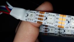
No. WS2813 uses a single-wire data protocol only. As one user put it, “WS2813 do not have a CLOCK line.” Connect only the data input (DI) and power. [Elektroda, OliJot86, post #18511427]
What is the BI pad on WS2813, and how should I connect it?
BI is the backup data line. Drive your strip from DI. Treat BI as the redundancy input used by some controllers. For simple ESP8266 control, leave BI alone. [Elektroda, marcingebus, post #18511550]
Do I need a bidirectional level shifter, or is unidirectional enough?
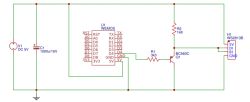
Unidirectional is enough because data only flows from MCU to strip. The Tasmota wiring uses a simple NPN level shifter to raise 3.3 V to WS2813-friendly levels. [Elektroda, khoam, post #18513061]
Is the Tasmota NPN circuit valid if the transistor seems always on?
Yes. “Around 4 V is the high state for WS2813 supplied from 5 V,” so the emitter output works. A single NPN inverter would flip logic and require library changes. Use the proven emitter follower arrangement. [Elektroda, ekrzychoooo, post #18526173]
Will a 74HCT1G08 work better than a transistor level shifter?
Yes. A 74HCT1G08 can shift 3.3 V to valid 5 V logic and sharpen edges. It also reduces component count versus a transistor and two resistors. [Elektroda, OliJot86, post #18513291]
Which Arduino library supports WS2813 on ESP8266 with examples?
FastLED supports ESP8266 and offers many effect examples. Users recommend trying it when debugging WS2813 behavior and timing on this MCU. [Elektroda, khoam, post #18513292]
Which library did the OP use initially for testing?
They used the “Neopixel by Makuna” library and searched examples for WS2813 support. That helped confirm the strip responded. [Elektroda, marcingebus, post #18513210]
Can the first WS2813 LED be used as a "signal booster"?
Yes, some approaches isolate the first LED to regenerate a clean 5 V signal for the rest. This method requires cutting the first LED from the strip segment. Others propose feeding data through two diodes to lift the drive level. [Elektroda, JanuszKornas, post #18511721]
How should I wire ESP8266 to WS2813 safely?
- Add a unidirectional 3.3 V → 5 V level shifter between ESP8266 GPIO and strip DI.
- Connect 5 V and GND to the strip; share GND with the ESP8266.
- Leave BI unconnected for basic control; no clock pin is required. [Elektroda, khoam, post #18513061]
Should I tie DI and BI together at the strip input?
No. BI is a backup line. Drive DI from the ESP8266 and let the strip handle redundancy internally. This matches typical guidance. [Elektroda, marcingebus, post #18511550]
Why does my strip power up solid red or white?
The first pixel can latch incorrect data or start in an undefined state when fed 3.3 V. Level shifting and clean power resolve this startup color lock. Users reported persistent red or random white/blue on first power. [Elektroda, marcingebus, post #18511388]
Can I drive WS2813 directly from 3.3 V without level shifting?
It’s unreliable at 5 V supply. The effective high-level is about 4 V, so 3.3 V can misread. Use a level shifter or lower VDD appropriately with care. [Elektroda, ekrzychoooo, post #18526173]
Which ESP8266 pin did users connect in DMA-based examples?
Examples often used GPIO3 with DMA, connecting it to the strip’s DI. This worked for basic tests and animations. [Elektroda, marcingebus, post #18511388]


