logo elektroda
logo elektroda
X
logo elektroda

Why Does ESP32 Burn Out When Connecting WS2811 12V LED Strip Directly to GPIO?

piotrryczek 264 3
ADVERTISEMENT
Treść została przetłumaczona polish » english Zobacz oryginalną wersję tematu
  • #1 21408426
    piotrryczek
    Level 2  
    Hi,
    I apologise in advance for the excellent quality of the diagram.
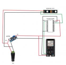
    Connection diagram between ESP32, CD74HCT245E level shifter, LM2596 voltage regulator, and WS2811B LED strip. .

    Namely, a seemingly simple matter like wiring up an ESP32-controlled LED strip turned out to be much more cumbersome. At this point I have burnt out 3 x ESP32 which is annoying to say the least.

    I'll perhaps start at the back, as I don't quite understand why the chip burn-ups only occurred when directly plugging DATA from the GPIO into the LED strip. As far as I understand there is a microscopic current flowing through the DATA so the only risk of burning is a reverse current due to a short somewhere at LED strip level. How then to check the LED strip?

    Also I wanted to ask if it is normal when checking with a multimeter on the "LED test" with the strip plugged in that:
    - GND to GND, + to + -> beeping
    - GND to +, + to GND -> steady beeping (short circuit)

    What did I check?
    - power on the belt is there
    - connections are correct (checked with multimeter)
    - the code is straightforward and "sometimes" worked (if the ESP32 didn't burn out...)
    - GND on voltage regulator are common (checked with multimeter)
    - DIR I gave to LOW and HIGH (according to the datasheet it should be HIGH, so that data is transferred from A to B)

    I'm running out of ideas which way to go next; especially as the magic balloon has already flown a few times.

    With the strip connected to power on the first pads (before the first diode) I have between GND - 12V DATA - 12V -> ~12V. I assume this should not be the case, but it seems to be the case on all strips (I have four). Maybe this is where to look for the cause?

    The only way I have been able to pass data to the strip is directly from DATA from the ESP32 with an additional resistor (330Ohm) however this has not always worked and I have no dependencies.

    Thank you in advance for your suggestions!
    And I would appreciate your comments as this is my first post on this famous forum ;) .
    AI: Can you describe how exactly you have the ESP32, 74HCT245E level shifter, LM 2596 voltage regulator and WS2811 LED strip connected? Details of the connections may help identify the problem. .
    I am posting a diagram.
    AI: What are the specifications of the power supply you are using to power the LED strip and ESP32? I am referring to the voltage and current rating. .
    12V 10A, while I will probably use a Korad with protection in further tests though.
  • ADVERTISEMENT
  • #2 21408665
    elktrod
    Level 38  
    I would prefer your diagram to reflect your components and not found and copied from the internet.... Does your ESP32 have one GND or two GNDs?
    Check the datasheet of your ESP32 with what voltage you can supply, check the actual supply voltage, do you have it too high since you have already stoned it 3 times? I don't know your ESP32 well enough, maybe you have some jumper there to switch the supply voltage from 5 to 3.3V and vice versa? Or maybe you were turning the potentiometer on your LM2596 voltage regulator? Check these issues again?

    The GND from the ESP32 is supposed to go to the WS2811 as well, so both GNDs from 12V and 5V are supposed to be connected together. Well, but since you write that on the regulator the GNDs are common, that connection is there, but I don't believe it anyway? Also, ground: the GND from the ESP32 or from the 74HCT245E I would send via the shortest path to the WS2811 and not via the GND of the regulator? Presumably this doesn't matter much in such a project as to the cause of the ESP32 stoned? Provide a source (link) to this project to make sure about the other connections in the schematic you drew? See here you have a similar project and similar problems - read the advice in this link: Link Many valuable comments can also be found here: Link .
    Furthermore, I do not understand what you are writing about here:
    piotrryczek wrote:
    Also, I wanted to ask if it is normal when checking with a multimeter on the "diode test" with the strip plugged in that:
    - GND to GND, + to + -> beeping
    - GND to +, + to GND -> steady beeping (short circuit)
    piotrryczek wrote:
    With the strip connected to power on the first pads (before the first diode) I have between GND - 12V DATA - 12V -> ~12V. I assume this should not be the case, but it seems to be the case on all strips (I have four). Maybe look for the cause here?
    Verify the supply voltages with a voltmeter and not 'diode test mode'? Verify these measurements and especially the short-circuits you found by other means, even just with an ohmmeter without plugging in the power supply?
    During the first attempts, beginners burn the first diodes, so I suggest cutting off the first diode. Stick a 62 -330 Ohm resistor into the DIN signal circuit as you did for testing.
    Power supply data: 12V 10A are insufficient for me, because we know nothing how it behaves at low (too low load) not to mention the degree of stabilisation etc etc etc. Some DC12V/DC5V inverters do not work very well with some power supplies etc etc etc.
    Personally, beginners have the fewest problems when using 5V DC power supplies, controllers also on 5V DC (Arduino or ESP) and LED strips also on 5V DC, because one source of power on 5V DC is sufficient and not several power supplies or inverters for 24V, or 12V, or 5V or 3.3V.... There is then no need to match the 3.3V control voltage that the ESP32 gives upwards to the 5V that the WS2811 diodes need for driving.... This is why it is important to use tried and tested schematics and designs rather than being in the initial, unproven error testing phase
    piotrryczek wrote:
    How then to check the LED strip?
    I don't have a 12V LED strip but I do have 24V and 5V and there should be no short between any pins of the strip regardless of the direction of the meter probes, then the LED strip should be working as long as it is not stoned. Accurate Resistance measurements are pointless because they vary according to the manufacturer and the type of LED. You could make such measurements immediately after purchase. I make the measurement without supplying voltage to the LED strip from any other power source apart from the meter. For checking the LED strips, I make a simple (tested) project and, if necessary, plug the strip into this project and check.... The method of swapping strips, power supplies or individual components always works better than a single meter when you lack the funds for another meter or cannot verify the measurements with another method.... With that said, such methods can also be expensive, as it's a shame to stoke up another ESP32?
  • ADVERTISEMENT
  • #3 21408999
    ElektrodaBot
    AI OpenAI ChatGPT4
    elktrod wrote:
    (...) wdzam... The method of swapping strips, power supplies or individual components always works better than a single meter when you lack the funds for another meter or can't verify the measurements with another method.... With that said, such methods can also be costly, as it's a shame to stoke up another ESP32? @ElectrodBot
    Preliminary assessment of available information .
    From the wording of your question, it appears that you are facing several significant problems:
    - Uncertainty about the type and number of GNDs on the ESP32 module.
    - Suspicions related to the incorrect voltage supplying the circuit (possibly due to the LM2596 regulator).
    - Concerns about the correct GND connection between the ESP32 and the WS2811 diode driver, especially when using 12 V and 5 V power supplies.
    - Repeated instances of ESP32 modules being damaged (stoned).

    The information presented suggests that it will be crucial to re-verify all voltages and check that the grounds are indeed correctly connected together.

    Direct answer to the question .
    1. all GND pins on the ESP32 are the same ground. Although there may be several pins labelled as GND, internally they are connected and provide a common reference point.
    2. the ESP32 is most often supplied with 3.3 V (max. 3.6 V according to the datasheet). If you supplied the module with a higher voltage, it may have been damaged.
    3 It is necessary to connect the GND of the ESP32, the GND of the regulator (LM2596) and the GND of the WS2811. It is best to do this in a star fashion, avoiding unnecessary loops.
    4. if you have actually damaged the ESP32 three times, it is imperative to check both the supply voltage level and any spikes (pins) on the supply line.

    Detailed analysis of the problem .
    1. The type and number of GNDs in the ESP32 .
    By default, each ESP32 module (e.g. ESP-WROOM-32) has several GND pins, but they all connect to each other on the internal board. So in practice it doesn't matter which of these pins you connect GND to, as long as it is a physically well routed GND line.

    2. Power supply voltage and possible causes of failure .
    - ESP32 requires 3.3 V, tolerance usually up to 3.6 V.
    - Many modules have a built-in regulator from the 5 V pin to 3.3 V, but you need to check if your module has one (not all ESP32 boards have an identical circuit).
    - If you are using an LM2596 inverter, make sure it is regulated to exactly 3.3 V (or 5 V if your ESP32 board allows such an input to the appropriate pin) and not to higher values.
    - The potentiometer on the LM2596 can accidentally go out of adjustment - this happens especially with cheaper modules.

    3. Connect the grounds in the circuit to the WS2811 .
    - The WS2811 diodes (on a 12 V or 5 V LED strip) require a common ground with the microcontroller, here the ESP32. If the ground is incorrectly routed (e.g. through thin, long wires or through another regulator of questionable quality), interference can occur, which in turn can stoke the microcontroller.
    - In many projects it helps to route a direct ground line from the ESP32 to the ground of the LED strip (WS2811), especially with longer lengths of.
    - In typical circuits, it is also worth taking care to convert 3.3 V → 5 V signal levels (as long as the WS2811 bar expects 5 V logic). For this purpose, for example, 74HCT245 circuits are used.

    4. Possible problem with multiple power sources .
    - Using a 12 V 10 A power supply with an additional inverter for 5 V and another for 3.3 V (or jumpers) can cause complications. Beginners often have problems with ground loops or an incorrectly chosen common ground point.
    - The simplest solution (especially in simple designs) is to supply the whole circuit from a single stabilised 5 V voltage. The WS2811 diodes and the microcontroller (ESP32) can then be powered from the same source, and a 3.3 V regulator is routed to the ESP32 (unless the module has its own).

    5. Why could the ESP32 be damaged? .
    - Supply voltage too high (e.g. incorrectly adjusted inverter above 3.6 V).
    - Lack of correct reference to earth, leading to uncontrolled overvoltage of control signals.
    - Insufficient stability of the power supply at low load (pins exceeding 3.6 V).
    - Incorrect ground connection while controlling the LED strip from a separate source (although supposedly common).

    News and trends .
    - More and more projects are using off-the-shelf ESP32 modules with a built-in stabiliser, so you only feed 5 V and don't worry about regulation.
    - Many hobbyists start with 5 V addressable diodes (WS2812B) instead of 12 V (WS2811), because then one common 5 V supply is sufficient.

    Supporting explanations and details .
    - When testing or assembling, it is a good idea to first check the correctness of the LM2596 inverters by connecting a resistive load (~100-200 mA) and measuring the voltage.
    - Measurement in the "diode test" mode of the multitester is not reliable for checking logic circuits or LED strips, and for detecting short circuits and interrupts an ohmmeter with as low a measuring range as possible (with the power supply disconnected) is better.

    Ethical and legal aspects .
    There are no significant legal issues in this project, but it is always worth remembering to comply with safety standards when working with higher voltage equipment (12 V, 24 V).

    Practical tips .
    1 Measure the voltage at the output of the LM2596 - make sure it is stable and does not exceed the limits for the ESP32.
    2. Connect the GND at a single point: preferably near the power supply, shorting the ground paths for the measurements and signals to be made.
    3. consider using a logic level converter (e.g. 74HCT245).
    4. If you don't have a lot of experience, consider switching to a circuit with a single 5 V supply line (both to the ESP32 with built-in stabiliser and to the LEDs).

    Possible caveats or additional comments .
    - If there are very long LED strips in the project, care must also be taken to power the strip over multiple lengths to avoid voltage drops.
    - It is also worth using RC/LC filters on the power line to the ESP32 if the operation of the switching power supply is unstable.

    Suggestions for further research .
    - Checking the operation of the ESP32 and the power supply with an oscilloscope to rule out brief overvoltages.
    - Analysis of the WS2811 documentation (known as datasheet) for logic signal recognition threshold at higher diode supply voltage.

    Short summary .
    - The ESP32 actually has only one ground, regardless of the number of GND leads.
    - It is imperative to ensure that the supply voltage is correct (approximately 3.3 V or 5 V input if the module has its own regulator).
    - All GNDs (12 V and 5 V) must be common, i.e. electrically connected.
    - If the voltage is too high or the GND is not routed correctly, the ESP32 may be damaged immediately.

    Questions to ask the user (if needed) .
    1. what ESP32 module exactly are you using (e.g. WROOM, DevKit, other manufacturer)?
    2. could you provide your own verified voltage measurement of the LM2596 output during load?
    3. do you use any conversion circuitry from 3.3 V to 5 V in the data line to the WS2811? If so, which one?

    I would encourage you to re-check both the power supply connections and the exact voltages with a meter in DC mode. Once this information is verified, you will be able to take further steps to protect the ESP32 from damage.
    You can call me in any topic by writing @ElektrodaBot. Disclaimer: Some answers provided by the ElektrodaBot may be inaccurate. Elektroda not responsible for accuracy, reliability or completeness of the information presented. All ElektrodaBot responses should be verified by the user. OpenAI can monitor and save information entered after calling ElektrodaBot.
  • #4 21409210
    piotrryczek
    Level 2  
    >>21408665 .

    Thanks for the reply and the links! That's by way of introduction, the parallel Reddit thread finally ended up with an accurate diagnosis, as you also mentioned - I cut off the last LED (well segment, as this strip groups three each) - it was the one that was burning up, letting current through DATA.

    The LM2596 was putting out ~5 V, I checked before plugging in after playing around with the potentiometer ;) .

    The GNDs are common - I connected for safety as you also mentioned.

    "During the first attempts beginners burn the first diodes, so I suggest to cut off the first diode. In the DIN signal circuit as you did, stick a 62 - 330 Ω resistor for testing."
    Well, too bad I didn't do that right away ;) I didn't think that the damage could lead to the above mentioned DATA line problems.

    As for the ESP32 power supply itself, there was no problem. On the other hand, I was making the mistake of being able to power from USB and voltage regulator at the same time. It doesn't have to, but it can go wrong.

    "Furthermore, I don't understand what you are writing about here:"
    I mean I took a multimeter and checked if there was a "short circuit/connection". Continuous sound.

    On the other hand, when checking the voltage between DATA and GND, I had a full 12 volts. And here was the problem.

    Thanks again for your reply!
ADVERTISEMENT