FAQ
TL;DR: At 11.5 V over a 5 m run, WS2811 control "goes crazy"; add series data resistors, solid decoupling, and correct MOSFET drive. [Elektroda, krajech, post #20733046]
Why it matters: WS2811 timing is tight, and long cables shrink noise margin—small supply drops can derail patterns in real projects.
Quick Facts
- WS2811 supply (VDD) spec: 3.5–5.5 V; keep it in-range despite cable drop and feed method. [WS2811 Datasheet]
- DIP WS2811 fed from 12 V via 2.7 kΩ measured about 5.8–5.9 V at VDD in this build. [Elektroda, krajech, post #20733086]
- About 33 Ω series resistor on DATA helps tame ringing on longer runs. [Elektroda, viayner, post #21215657]
- Local decoupling used here: 22 µF + 100 nF per node; long wiring may need more. [Elektroda, krajech, post #21215650]
- 5 m cable worked at 14 V but went unstable below 12 V—margin was tight. [Elektroda, krajech, post #20733046]
Why does my WS2811 chain work at 14 V but fail at 11.5 V over 5 m?
Your long cable raises signal distortion and voltage drop. At 14 V there’s extra headroom; at 11.5 V the logic margin shrinks and timing errors surface. That’s why the pattern goes unstable only at lower bus voltage. Improve margin with series data resistance and robust local decoupling. Verify with a scope at the controller and at the far end. [Elektroda, krajech, post #20733046]
How should I power the DIP WS2811 from a 12 V system safely?
Use the DIP reference method: feed VDD from 12 V through the specified resistor and decouple close to the IC. Ensure VDD remains within 3.5–5.5 V under load and cable drop. Keep the ground solid between data source and the WS2811. This preserves logic thresholds and timing integrity. [WS2811 Datasheet]
Do I need a series resistor on WS2811 data lines? Where should it go?
Yes. Add about 33 Ω in series with DATA at the driving end. It damps reflections, reduces overshoot, and slightly slows edges for cleaner timing. Place it right at the DO pin (or MCU output). "There was something about adding a resistor of about 33 ohms on the data lines." [Elektroda, viayner, post #21215657]
Shielded cable made my data worse—what should I use instead?
In your test, shielding worsened behavior. Use a twisted pair for DATA and GND to control impedance and maintain a firm reference. Keep the data return short and bonded. If you must use shield, bond it correctly and avoid floating shields along the run. [Elektroda, krajech, post #20732946]
How do I check if the DATA waveform is the problem?
Use an oscilloscope. Probe at the controller output and at the WS2811 input after the long cable. Compare rise/fall times, overshoot, and amplitude. Look for reflections, slow edges, or undershoot. "See what you have at the beginning of the cable and after 5 m." [Elektroda, viayner, post #20732981]
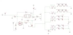
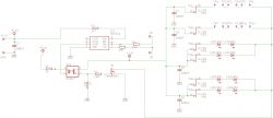
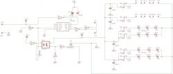
Why is a 20 Ω to GND and 220 kΩ to +12 V gate network problematic?
That network drives the gate asymmetrically. The 20 Ω pull-down is strong and fast, while the 220 kΩ pull-up is very weak and slow. You get long RC delays, noise susceptibility, and unpredictable switching. Use balanced, defined gate drive instead. [Elektroda, Andrzej42, post #20732986]
How should I drive a MOSFET from WS2811 safely?
Drive an N‑MOSFET low‑side. Add 10 Ω in series with the gate, and a 10 kΩ gate pull‑down to ground. Keep LED current path separate and referenced. If isolating, place the optocoupler before the gate network and size currents correctly. [Elektroda, HD-VIDEO, post #20733124]
Do I need an optocoupler (PC817) here, and how should I bias it?
Only use it if you need isolation. Bias its LED for adequate current so the transistor switches cleanly; around 10–16 mA is typical here. Connect the opto LED from +supply through a resistor to the WS2811 OUT, then use the transistor to pull the MOSFET gate via a 10 Ω/10 kΩ network. [Elektroda, HD-VIDEO, post #20733124]
Is PC817 fast enough for this application?
PC817 is a general‑purpose optocoupler with microsecond switching times. It’s fine for on/off LED loads but too slow for high‑speed data paths. Use it only in the MOSFET gate path, not on the WS2811 data line. Keep IF high enough to avoid sluggish edges. [PC817 Datasheet]
Can I leave unused WS2811 outputs floating?
Yes. WS2811 outputs are controlled current sinks; leaving an unused channel open is acceptable. Do not tie unused OUT pins to VDD. Still decouple the IC and keep the ground solid to avoid coupling noise into active channels. [WS2811 Datasheet]
Why might one WS2811 chip fail in a long "light hose" after weeks?
Long wires behave like inductors and antennas, producing transients that stress the IC. Weak or missing decoupling increases risk. Add adequate capacitance near each WS2811 and tame data edges with a small series resistor. This reduces spikes and ESD‑like events. [Elektroda, viayner, post #21215634]
Where should I put the series resistor on DO, and what value?
Place a small series resistor at the signal source, right at DO. Values around 33 Ω are common for damping. Large values excessively slow edges and reduce logic high amplitude, causing misreads. Keep the ground return tight alongside the data conductor. [Elektroda, viayner, post #21215657]
What data rate does WS2811 use, and why does it matter for wiring?
WS2811 uses an approximately 800 kHz one‑wire timing protocol. Fast edges and tight timing demand clean, well‑referenced transmission over distance. Long cables increase capacitance and reflections, so use series damping, short stubs, and good decoupling to preserve margins. [WS2811 Datasheet]
How do I stabilize a 5 m WS2811 segment quickly?
- Add about 33 Ω in series with DATA at the source.
- Place 100 nF + 22 µF decoupling at every WS2811 VDD/GND pair.
- Measure with a scope at both ends and tweak resistor value for the cleanest edges. [Elektroda, viayner, post #21215657]
One node died and the chain misbehaves—what can I expect?
A single failed WS2811 can disrupt the cascade and randomize downstream behavior. Plan for field replacement and protect nodes with proper decoupling and series resistors. Watch for intermittent faults that appear after weeks of operation. [Elektroda, krajech, post #21215621]
 .
.
 .
.


