FAQ
TL;DR: Only 1 safe external-interrupt pin (D7) remains with the 0.66" OLED shield; “the ESP will not start” if D3/D4 are low. Use the RFM69_ATC constructor to move DIO0 off D2 and keep I2C on D1/D2. [Elektroda, khoam, post #18645179]
Why it matters: This helps Wemos D1 mini builders fix IRQ/I2C pin conflicts when pairing an RFM69 with the 0.66" OLED shield.
For: ESP8266/Wemos D1 mini users integrating an RFM69 transceiver and the 0.66" I2C OLED who need to reassign pins cleanly.
Quick Facts
- ESP8266 default I2C is D2 (SDA) and D1 (SCL); override with Wire.begin(sda, scl). [Elektroda, khoam, post #18644353]
- Set RFM69 pins in code via RFM69_ATC(ssPin, irqPin, isHW); no need to edit RFM69.h. [Elektroda, khoam, post #18645179]
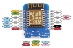
- D0 (GPIO16) supports 0 external interrupts; do not use it for RFM69 DIO0. [Elektroda, khoam, post #18645344]
- D3 (GPIO0) or D4 (GPIO2) low at boot can block startup; avoid using them for IRQ. [Elektroda, khoam, post #18645179]
- D8 (GPIO15) is internally pulled down; usable for IRQ with attention to default levels. [Elektroda, khoam, post #18645989]
How do I change the RFM69 DIO0-IRQ pin on a Wemos D1 mini?
Pass your chosen pins into the RFM69_ATC constructor instead of editing headers. Example: RFM69_ATC radio(SS_pin, IRQ_pin, false). Pick a GPIO that supports external interrupts and does not interfere with boot. Keep the OLED on D1/D2 and move DIO0 off D2. “You do not need to change anything in the RFM69.h file.” [Elektroda, khoam, post #18645179]
Which pin is safest for RFM69 IRQ with the 0.66" OLED shield attached?
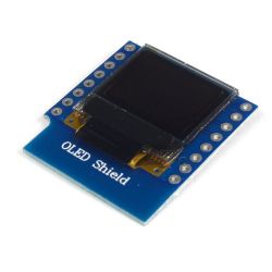
Use D7 (GPIO13) if available. On the 0.66" OLED shield, D7 is the only header pin left that supports external interrupts without affecting I2C. Avoid D3 and D4 for IRQ, because low level at boot can block startup. Keep the I2C display on D1/D2. [Elektroda, khoam, post #18645179]
Why does my ESP8266 fail to boot when IRQ is on D3 or D4?
D3 (GPIO0) and D4 (GPIO2) are bootstrapping pins. If either is held low at power-up, normal boot fails. An RFM69 wired to these can pull them low and stop the chip from starting. As the expert noted, “the ESP will not start” if those pins read low at boot. Move IRQ away from D3/D4. [Elektroda, khoam, post #18645179]
Can I use D8 (GPIO15) for the RFM69 DIO0-IRQ?
Yes, you generally can route RFM69 DIO0 to D8. Note that D8 has an internal pulldown to GND on ESP8266 boards. Ensure your wiring and module states won’t conflict with the boot mode that requires GPIO15 low. Test with clean power cycles after wiring. [Elektroda, khoam, post #18645989]
Is D0 (GPIO16) suitable for RFM69 IRQ?
No. D0 (GPIO16) does not support external interrupts on ESP8266. It cannot trigger the RFM69 receive interrupt line. Use a different GPIO that supports external interrupts, such as D7 or D8, depending on your wiring constraints. This pin has 0 usable external interrupts. [Elektroda, khoam, post #18645344]
Can the OLED and RFM69 share any pins (I2C or IRQ)?
No. Do not share the I2C pins with RFM69 IRQ or other signals. The IRQ line must be dedicated, and the OLED needs SDA/SCL to remain on their bus. Sharing would cause bus contention or spurious interrupts. Keep IRQ separate and leave D1/D2 for the display. [Elektroda, khoam, post #18645499]
How do I move the RFM69 NSS/CS pin to avoid conflicts?
NSS (CS) is an input on the RFM69, so you can move it to a different GPIO. Select a pin that does not affect boot. Then pass the new SS pin as the first argument to the RFM69_ATC constructor. Verify SPI wiring after changes. [Elektroda, khoam, post #18645866]
What wiring and code combo has been proven to work with this setup?
A reported fix: swap RFM69 IRQ and NSS, then put NSS on D3 and IRQ on D8. Update code to: RFM69_ATC radio(D3, D8, false). How-To: 1. Move RFM69 DIO0 to D8 and NSS to D3. 2. Change the constructor pins accordingly. 3. Power-cycle and test radio receive/ACK. This freed D1/D2 for the OLED and booted cleanly. [Elektroda, pier, post #18646084]
How do I reassign I2C SDA/SCL in code if I’m not using the shield defaults?
Call Wire.begin with your chosen pins. Example: Wire.begin(SDA_pin, SCL_pin). The default mapping on ESP8266 is SDA=D2 and SCL=D1 when called without arguments. Reassign only if your hardware wiring supports it. [Elektroda, khoam, post #18644353]
I must use D3 or D4 for IRQ—any workaround?
Insert an NPN-transistor inverter between RFM69 DIO0 and the ESP input so the ESP sees high at boot. The library sets interrupts on rising edge; if inverted, you may need to switch to falling edge in RFM69.cpp. Quote: “set interrupts on the rising edge.” Validate with scope if possible. [Elektroda, khoam, post #18645499]
What is the RFM69_ATC constructor signature and parameter order?
RFM69_ATC(uint8_t slaveSelectPin, uint8_t interruptPin, bool isRFM69HW=false, uint8_t interruptNum=0). Pass your chosen NSS (CS) pin first, then the IRQ pin. If you omit arguments, it uses library defaults defined for the platform. Prefer setting pins explicitly to avoid conflicts. [Elektroda, khoam, post #18645179]
Why does my sketch say ‘Blink’ not declared, and how do I fix it?
Add a forward declaration at the top of your sketch: void Blink(byte PIN, int DELAY_MS); This tells the compiler about the function before use. Then keep the definition later in the file. Recompile to confirm the error is gone. [Elektroda, khoam, post #18646109]
LED doesn’t blink on receive—what should I check on the D1 mini?
Set pinMode for the LED once in setup(), not every call. LED_BUILTIN maps to D4 (GPIO2) on the D1 mini. Ensure you are not simultaneously using D4 for another function like boot-strapping or IRQ. Then toggle the pin to test visually. [Elektroda, khoam, post #18646149]


