logo elektroda
logo elektroda
X
logo elektroda

Connecting ESP8266 to 10016BH display - how to read the status?

evolucja 1233 20
ADVERTISEMENT
Treść została przetłumaczona polish » english Zobacz oryginalną wersję tematu
  • #1 18645646
    evolucja
    Level 20  
    Hi,
    I have this problem.

    I would like to read the status of a 7 segment display from one device (controlled by a controller from the board of that device, you know) using an external ESP8266.

    The model of the display is 10016BH (10 pin).

    How can and should I hook up to this display to read the state of each segment using the GPIO on the ESP8266?


    Thank you in advance :) .
  • ADVERTISEMENT
  • #2 18645712
    dasej
    Level 32  
    Welcome.

    How many digits?
  • ADVERTISEMENT
  • #3 18645717
    BlueDraco
    MCUs specialist
    You look at the leads in the datasheet and already know where to pin. You read the state of the 7 lines and compare with the prepared pattern board to find the displayed digit.
  • #4 18645758
    evolucja
    Level 20  
    dasej wrote:
    How many digits?

    One :) .

    BlueDraco wrote:
    You look at the leads in the datasheet and already know where to clip. You read the state of the 7 lines and compare with the prepared pattern table to find the displayed digit.
    .
    So I can directly connect the GPIO to the display lead? Nothing will happen to the other controller and the display if the GPIO on the ESP8266 accidentally acts as an output and not an input and a voltage appears?
  • #5 18645781
    dasej
    Level 32  
    As the GPIO in the ESP will be as output there may be a problem.
    Therefore, give resistors.
    This is how you can connect.
  • #6 18645785
    khoam
    Level 42  
    evolucja wrote:
    Nothing will happen to this other controller and display if the GPIO in the ESP8266 accidentally triggers as output and not input and a voltage appears?
    .
    If it "acts" as an output in the ESP8266 GPIO, that would be a problem. I don't really understand how this could happen "by accident", but programmatically it is possible :) What voltage is supplied to the diodes in the display segments?
  • #7 18645801
    evolucja
    Level 20  
    khoam wrote:
    If it "works" as an output in the GPIO of the ESP8266, that would be a problem. I don't really understand how this could happen "by accident", but programmatically it is possible What voltage is supplied to the diodes in the display segments?
    .
    On the meter 5V before the resistor, ~2V after the resistor, SMD resistor 308 - that is probably 3GΩ.

    On the display + is common, - flies through the resistor

    ESP is obviously running at 3.3V.

    As for the case, I would prefer to protect myself, I don't know what happens to the ESP pins when programming etc.... I don't want to mess up the other board. Would a diode, for example, fit so that only one way the signal flies, or am I thinking too simply? :)
  • #8 18645808
    khoam
    Level 42  
    evolucja wrote:
    Which is the case, I would prefer to protect myself, I don't know what happens to ESP pins when programming etc.
    .
    Not every pin on the ESP8266 will be suitable for this. Please see the link below for restrictions on what certain pins can do.
    https://randomnerdtutorials.com/esp8266-pinout-reference-gpios/

    evolucja wrote:
    Would any diode, for example, fit so that only one way the signal goes
    .
    Yes, a Schottky diode with a small conduction voltage drop.
  • ADVERTISEMENT
  • #9 18645819
    dasej
    Level 32  
    evolucja wrote:
    .... SMD resistor 308 - which is probably 3GΩ.
    ....
    Would a diode, for example, fit so that only one way the signal flies, or am I thinking too simply? :)
    .

    SMD 308 is a code designation not a value.
    The diode falls off.

    308 or 30B ( 2Koms) measure!
  • #10 18645842
    evolucja
    Level 20  
    dasej wrote:
    308 or 30B ( 2Koms) headed!


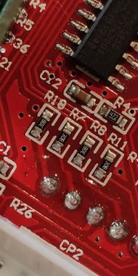
    Actually 30B. You can clearly see.

    Connecting ESP8266 to 10016BH display - how to read the status? .

    That is, the diodes are flying on 5V with a 2kΩ resistor, and a 3.3V signal would have to go to the ESP. Any ideas? :(
  • #11 18645994
    khoam
    Level 42  
    Determine perhaps to start with, according to the measurement, which voltage value will be the "high" and which will be the "low" state.
  • ADVERTISEMENT
  • #12 18646107
    evolucja
    Level 20  
    khoam wrote:
    what voltage value would be the "high" state and what would be the "low" state.
    .
    For the ESP or this STC? How do you measure this? :(

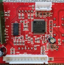
    I am attaching a picture of the board. Maybe from this it will be easier to determine something.
    The main controller is an STC8A8K64S4A12.
    The diodes are connected to something called a "74HC595 sliding register".

    Connecting ESP8266 to 10016BH display - how to read the status? .
  • #13 18646116
    khoam
    Level 42  
    evolucja wrote:
    For ESP or this STC?
    .
    Do the voltage measurement directly at this location from where you will take the status information for ESP.
    What is the name of this module? Maybe a schematic can be found.
  • #14 18646196
    evolucja
    Level 20  
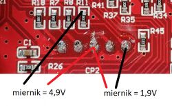
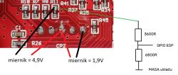
    When the segment is lit, there is 1.9V behind the 30B resistor and 4.9V in front of the resistor.
    Values from a plug-in meter as shown in the photo.
    When the segment is not lit, it is 0V.

    Connecting ESP8266 to 10016BH display - how to read the status? .
  • #15 18646324
    khoam
    Level 42  
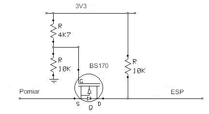
    So you can use a 1V9/3V3 logic state converter. Schematic suggestion below (one channel). You may have to use, for example, a BSS138 with a lower Gate Threshold Voltage instead of the BS170 transistor.

    Connecting ESP8266 to 10016BH display - how to read the status? .

    Feeding 1V9 to the input of the circuit will result in 3V3 at the output. Passing 0 to the input, will force a low state at the output for the ESP. The ESP and controller grounds must be connected.
  • #16 18646398
    dasej
    Level 32  
    Give the resistors alone and it will be OK.

    Connecting ESP8266 to 10016BH display - how to read the status? .
  • #17 18646414
    khoam
    Level 42  
    evolucja wrote:
    When the segment is not lit, it is 0V.

    Also where the measurement previously showed 4.9 volts?
  • #18 18648150
    ArturAVS
    Moderator
    If it's a display with a common anode, the active state is logic 0(the 595 register at the output of the active segment gives an L state). The easiest way is to enable the pull-ups in the ESP(high state forcing) and through the shottky diodes connect to 595(the active output will pull down to logic zero the ESP input).
  • #19 18648428
    khoam
    Level 42  
    ArturAVS wrote:
    If it's a display with a common anode, the active state is logic 0 (the 595 register at the output of the active segment gives an L state). The easiest way is to turn on the pull-ups in the ESP(high state forcing) and through the shottky diodes connect to 595(active output will pull down to logic zero the ESP input).
    .
    This solution is OK, but is unlikely to prevent the ESP pin from "accidentally" switching from input to output mode as requested by the Author.;)
  • #20 18648704
    tmf
    VIP Meritorious for electroda.pl
    evolucja wrote:
    Diodes are plugged into something called a "74HC595 sliding register".
    .
    If you've got a 595 register there, then instead of combining, hook up to the serial input of that register - you've got SCK, MOSI, SS - you hook that up to SPI in slave mode and you've got a readout of what the processor is sending to the latch. Even if you need to convert levels, you only have 3 signals, not 7 or 8.
  • #21 18648712
    ArturAVS
    Moderator
    Just add some more series resistors which will limit the "collision" current . Although it might be worthwhile, instead of reading the state of the segments, to simply listen for transmissions to the 595?

Topic summary

The discussion revolves around connecting an ESP8266 microcontroller to a 10016BH 7-segment display to read the status of its segments. The user seeks guidance on how to hook up the ESP8266 GPIO pins to the display leads without damaging either device. Responses suggest checking the display's datasheet for pin configuration and using resistors for protection. Concerns are raised about the ESP8266 GPIO accidentally acting as an output, which could cause issues. Voltage measurements indicate that the display operates at 5V with a 2kΩ resistor, while the ESP8266 operates at 3.3V. Suggestions include using Schottky diodes for signal protection and considering a logic level converter to ensure compatibility between the 5V display and the 3.3V ESP8266. Additionally, connecting to the 74HC595 shift register used in the display is proposed as an alternative method to read the segment states.
Summary generated by the language model.
ADVERTISEMENT