logo elektroda
logo elektroda
X
logo elektroda

ESP8266, PCF8574 and 7-segment LED how to connect it correctly?

CiekawyŚwiata 2067 30
ADVERTISEMENT
Treść została przetłumaczona polish » english Zobacz oryginalną wersję tematu
  • #1 19259318
    CiekawyŚwiata
    Level 4  
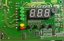
    I want to use the ESP8266 (actually nodemcu v3) and the PCF8574 to read the status of a 7-segment LED in another device (three to be precise).
    From the PCF8574 datasheet I read that the supply voltage should be between 2.5 to 6V which means that, at least theoretically, it should work from a 3.3V supply just like the nodemcu, however, I can also read (in the datasheet) that "VIH High-level input voltage" should be from the range of 0.7 × VCC VCC + 0.5 which means that in the case of a 3.3V supply, for the high state a minimum of 2.31V and a maximum of 3.8V is needed, while "VIL Low-level input voltage" from the range –0.5 0.3 × VCC i.e. -0.5V to 0.99V
    I don't really know how to determine what the maximum voltage can be on these 7-segment LEDs their designation is KT10521BJ1B-A unfortunately I couldn't find an datasheet for exactly this model.
    I am wondering how to safely connect the PCF8574 to these 7-segment LEDs, Will it be safe directly for both the device I want to read the information from and mine. Or should I use a voltage divider on each input and additionally (or only) connect a resistor in series that will limit the current flow to a maximum of a few mA i.e. 4k7 ESP8266, PCF8574 and 7-segment LED how to connect it correctly? .
  • ADVERTISEMENT
  • #2 19259413
    tos18
    Level 42  
    The voltage you will be working on is the supply voltage of this atmega (just measure it).
    I would not take the signals from the display but from the atmega.

    The display is sequential(read) and additionally the keyboard works on the same lines.

    You will need 12 lines to read data from the display.
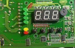
    I think the most convenient places to plug in are the lower fields of resistors 221 (data) and the vias next to the top green LED that is the transistor base control before resistors 102 ( selected digit)

    ESP8266, PCF8574 and 7-segment LED how to connect it correctly? .

    Show the other side of the board maybe these signals are on the prog and test connectors or maybe the device has some serial communication and you won't need to read the displays
  • #3 19259469
    CiekawyŚwiata
    Level 4  
    Unfortunately I don't have very good pictures of the other side those described as test on the other side are probably connected to the temperature sensors which are in the picture in the first post on the right. I was planning to use 24 lines for the display readout, I have a couple of PCF8547's and three I wanted to use for the segmented ones and one for those other 6 leds through, am I wrong or are those 6 leds controlled identically to the segmented ones? I was wondering, when I tried to measure the voltage on these leds (one and the other) with a meter, it showed some strange things, it could show lower voltage on a led that is not lit than on one that is lit, is it because they are not lit all the time but "blink" (they are multiplexed)? In general, these small LEDs are so obviously at least some of them even when lit do not light up at full power
    Maybe not a clever question, but how do I know the status by connecting to the resistors and to the bases of the transistors? Do I understand correctly that each of these transistors is responsible for "lighting up" one segment and on resistors I can find information which elements of the segment should be lit up and which remain blank? So you have to read the states on the resistors all the time and find out which transistor is currently conducting?


    I would also like to ask you a question, because I know (I assume) that the ULN on the left side of the atmega is used to control relays, but what is the circuit on the right side? I've tried to find it by designation but have not been able to figure out what it is.

    Tomorrow I'll take more detailed pictures from underneath and measure the voltage on the atmega
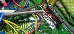
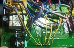
    That second photo is those test prog vias (by those yellow/green wires) and the first one is on the other side near the atmega (atmega somewhere on the top left I think)
    ESP8266, PCF8574 and 7-segment LED how to connect it correctly?
    .
    ESP8266, PCF8574 and 7-segment LED how to connect it correctly? .
  • ADVERTISEMENT
  • #4 19259513
    rubik123
    Level 21  
    And I'm intrigued by the ULN2003 housing. Cut and it works?...And it's photo is so silly.... he, he.
  • #5 19259522
    tos18
    Level 42  
    CiekawyŚwiata wrote:
    For the display readout I was planning to use 24 lines, I have a couple of PCF8547s and three I wanted to use for those segmented ones and one for those other 6 leds through?


    There is no point. You will read everything through these 12 lines

    CiekawyŚwiata wrote:
    am I mistaken or are these 6 leds controlled identically to the segmented ones?
    .
    You are right - they are treated as a fourth display - read about sequential control(multiplexing) of displays

    CiekawyŚwiata wrote:
    Do I understand correctly that each of these transistors is responsible for "lighting up" one segment and on the resistors I will find information which elements of the segment are to light up and which remain blank?

    Yes.

    CiekawyŚwiata wrote:
    So that you have to read the states on the resistors all the time and catch which transistor is currently conducting?


    You're doing the right thing - just wait for 1 logic in front of the base of the transistor in question and when it comes up read the states of the lower resistors and so on 4 times. And if you get it right you can read the state of the buttons too.
    To check if something has changed you can use the INT output of the pcfa which will read these 4 lines.
    CiekawyŚwiata wrote:
    what is that circuit on the right?
    .
    LM324 - 4x operational amplifier
  • ADVERTISEMENT
  • #6 19259538
    janek_wro
    Level 29  
    CiekawyŚwiata wrote:
    I want to use the ESP8266 (actually nodemcu v3) and PCF8574 to read the state of a 7-segment LED in another device (three to be precise)
    And is there any technical justification for constructing such a prosthesis? Because maybe the issue needs to be bitten differently. What do you ultimately want to achieve?
    The board is probably some kind of Compit boiler controller. What do you want to read from this LED? Temperatures, something else?
    Maybe the ESP8266 would handle the needed issue directly itself, instead of reading 7 segment LEDs?
  • #7 19259642
    CiekawyŚwiata
    Level 4  
    tos18 wrote:
    CiekawyŚwiata wrote:
    So that you have to read the states on the resistors constantly and catch which transistor is conducting at any given moment?
    .
    You're doing a good job - just wait for 1 logic in front of the base of the transistor in question and when it appears read the states of the lower resistors and so on 4 times. And if you get it right you can read the state of the buttons too.
    To check if something has changed you can use the INT output of the pcfa which will read these 4 lines.
    .

    I don't know if this won't overwhelm my programming skills :D .
    I understand that I would connect the four lines from before the transistors to the inputs on the PCF and the 8 lines from before the resistors to the other PCF.
    But what to connect under INT, how to synchronize it? Maybe it would be enough to read these 12 lines in a loop, check which of the first 4 lines is high and depending on that, switch on virtual diodes based on the state of the remaining 8 lines, in total, I think theoretically this is how it should work but the question is whether I will be able to read and process this data fast enough? Probably I can read them, but if I process them, I probably won't be able to do it fast enough, and if I read slower than the refresh rate, my virtual display may falsify, because one segment may still have the old information and the next one already changed after refreshing. Maybe I could do some kind of reading function and pass one of the transistor lines (preferably the first one) to the INT in the PCF (I think I'm right in thinking that it works like an interrupt) and when an interrupt occurs, in a fast loop check if the next transistor is already conducting and only when the switching occurs, read these other 8 lines after reading all four segments, process the data and wait for the next interrupt and in order not to do it with every interrupt it would be enough to activate the interrupt every few seconds (I don't need it more often).
    I may have messed up a bit and not needlessly elaborated, it would have to work. The question is whether I'm combining in the right way or whether it can be done in a simpler way? I need to check this san led once in a few seconds and if I can get satisfactory speed I2C is not super fast and this atmega refreshes it with maximum speed it can afford.

    janek_wro wrote:
    CiekawyŚwiata wrote:
    I want to use ESP8266 (actually nodemcu v3) and PCF8574 to read state of 7-segment LED in another device (three to be precise)
    And is there any technical justification to construct such a prosthesis? Because maybe the issue needs to be bitten differently. What do you ultimately want to achieve?
    The board is probably some kind of Compit boiler controller. What do you want to read from this LED? Temperatures, something else?
    Maybe the ESP8266 would handle the needed issue itself directly, instead of reading 7 segment LEDs?
    .
    I don't know if there is technical justification for this, but I want to be able to press one button on this controller remotely and I need to be able to check if the controller reacted correctly to the press (first of all, if the press worked and if it didn't accidentally count as several presses and what state the controller was in before the press). From the segmented display I can read errors, if any appear, and from these small LEDs I can see the condition of the boiler.. Probably with an ESP it would be possible to control the whole cooker without any problem and throw away the existing controller but I will definitely not do that. I want to interfere as little as possible with the existing controller, it's old and primitive but I'm happy with it. I was actually thinking of replacing the controller with a new one with WiFi and internet control but believe it or not there is no such thing, this one works under specific conditions that no new controller would allow. And maybe I'll learn something if it works out, I still have a few devices I'd like to connect to xD
  • #8 19259655
    tos18
    Level 42  
    CiekawyŚwiata wrote:
    But what to connect under the INT,

    one ESP input
    CiekawyŚwiata wrote:
    Maybe it would be enough to read these 12 lines in a loop, check on which of the first 4 is high and depending on this light up the virtual LEDs based on the state of the other 8 lines,

    You can, but why read 2 pcfs and waste your time ? you will hit the moment when the states change and the misrepresentation is ready.
    you check if INT is zero(you can use an interrupt) if yes you initiate a read.
    Virtual LEDs ...hmmm isn't it better to write out states for individual digits and other characters?
    then with a simple switch() - case decode the whole byte as a character or a digit ?
    You could also use an array for decoding.

    http://akademia.nettigo.pl/starter_kit_030/
    https://www.ti.com/lit/ds/symlink/pcf8574.pdf
  • #9 19259689
    CiekawyŚwiata
    Level 4  
    tos18 wrote:
    CiekawyŚwiata wrote:
    Maybe it would be enough to read these 12 lines in a loop, check on which of the first 4 is the high state and depending on this light the virtual diodes based on the state of the other 8 lines,
    .
    You can, but why read 2 pcfs and waste your time ? you will hit the moment when the states change and the misrepresentation is ready.
    you check if INT is zero(you can use an interrupt) if yes you initiate the read.

    I'm not sure I understand how this INT works in the PCF, I've looked at the datasheet and the library to handle it and I'm not sure, At first I thought I could set which pin of the PCF "observes" the INT and if something appears on it, it goes low (because as I understand it, normally if nothing happens, it goes high all the time). As I didn't find any information on how to set it, I came to the conclusion that it goes low if any of the PCF pins changes state (because as I understand it, it informs about a change from high state to low state and vice versa). Following this line of thought... I connect 4 lines with transistors to one PCF and 8 lines "with resistors" to the other one and now every time a transistor switches I will have on INT of the first one information about the change, am I right?

    tos18 wrote:
    Virtual diodes ...hmmm and isn't it better to write out the states for individual digits and other characters ?
    then with a simple switch() - case decode the whole byte as a character or digit ?
    You could also use an array for decoding.

    Such a mental shortcut :) no diodes will be present. Information from the controller in a textual way will be presented on a page hosted on esp on the local network and in the future sent to a web server.
  • #11 19260533
    janek_wro
    Level 29  
    CiekawyŚwiata wrote:
    I don't know if this is technically justifiable, but I want to be able to press one button on this controller remotely and I need to be able to check if the controller reacted properly to the press (above all if the press worked and if it didn't accidentally count as several presses and what state the controller is in before the press)
    After what you write, it looks like the approach is technically sound.
    As for the 'software push' button. You need to train yourself on the pulse length (can't be too short). Try around 100ms. Physical buttons certainly already have their debouncing. Either hardware (RC circuit) or additionally software. Also, you don't have to worry too much about the interpretation of multiple presses. You just have to make sure that there are no unforeseen glitches in the output.

    Your situation reminds me how many years ago (like 30+) I implemented a similar diwajs. Z80 was reading the output from ICL7107. In those days there were no high-resolution A/D converters available for hobbyists. If by some miracle one was found, they cost a fortune. So there was carving from what was at hand.
  • #12 19260960
    CiekawyŚwiata
    Level 4  
    janek_wro wrote:
    What about the "software push" button. You need to train yourself on the pulse length (can't be too short). Try around 100ms. Physical buttons certainly have their debouncing already. Either hardware (RC circuit) or additionally software. Also, you don't have to worry too much about the interpretation of multiple presses. You just make sure programmatically that no unforeseen glitches are output there.

    I have already control-soldered under the microstick today, with a time setting of 250ms everything looks ok, I can simulate its pressing from the phone without any problem. I will build a second prototype, connect it up and for the time being I will only use the button on the phone and only locally while standing by the boiler to test if any problems arise and in the meantime I will work on the LED readout.

    janek_wro wrote:
    Your situation reminds me of how I implemented a similar diway many years ago (like 30+). The Z80 was reading the output from an ICL7107. In those days there were no high resolution A/D converters available for hobbyists. If by some miracle one was found, they cost a fortune. So there was carving from what was at hand.

    It reminds me of how 30 years ago, as a kid, I used to drive a trolley and bring old broken TV sets and radios from the neighbouring villages and disassemble them at home, including soldering all the components off the circuit boards, and there was a lot of this in 2-3 years I took apart over a hundred pieces of equipment, after some time I did not have to go for them people brought them by themselves :D At that time for me it was the only available source of components and by the way great fun :D

    Back to the topic, today I took some new pictures of the controller (if it would be needed) I connected to the microstick and measured the voltage on the atmeda and unfortunately, although in total I probably did not expect it to be different, there is 5V exactly on the smd capacitor which is on the right side of the uPC directly on the atmeda I was afraid because the legs there thinner than the tips of my meter :) .
    Now I'm in a conundrum, because from what I've read from the PCF datasheet, if I supply 3.3V to the PCF, I can no longer give 5V to the inputs and I don't quite know how to solve this problem efficiently now. I have a few ideas but I don't know what will be good and won't cause more problems:
    1. power the PCF from 5V and insert a level shifter between the PCF and ESP, but this solution will probably slow down the already not so fast I2C
    2. connect PCF directly from ESP and power it from 3.3V and put a voltage divider on each PCF input, e.g. 6k8 and 10k resistors, but wouldn't this also cause a new problem?
    3) Switch to an Arduino powered from 5V, but I don't think I would like to run away from the problem, which I am sure can be solved using ESP and additionally I would have a problem with lack of WiFi.
  • ADVERTISEMENT
  • #13 19261395
    janek_wro
    Level 29  
    CiekawyŚwiata wrote:
    only such a solution will probably slow down the already not fastest I2C very much
    Oh and here you are wrong. There are integrated level shifters, and in ranges of hundreds of MHz.
    Here's a quick guide from TI, knowledge always comes in handy.
    https://www.ti.com/lit/SLYY165
    And you can use the BSS138+2 resistors if you want on foot. You can google the schematic after the keyword 'BSS138 level shifter'. I would put them in front of the PCF inputs, and chase the gates from the input signals, after adjusting accordingly.

    CiekawyŚwiata wrote:
    3. Switch to an Arduino powered from 5V
    No no, because of the voltage difference don't retreat to a lower architecture ;) .
  • #14 19261625
    tos18
    Level 42  
    janek_wro wrote:
    .
    Your situation reminds me of how I implemented a similar diwajs many years ago (like 30+). The Z80 was reading the output from an ICL7107. In those days there were no high resolution A/D converters available for hobbyists. If by some miracle one was found, they cost a fortune. So there was carving from what was at hand.
    .
    I used a C520D - resolution a little less but it read better.
    CiekawyŚwiata wrote:
    I have a few ideas but I don't know what will be good and not cause further problems:
    1. power the PCF from 5V and insert a level shifter between the PCF and the ESP, only this solution will probably slow down the already not so fast I2C
    2. connect PCF directly from ESP and power it from 3.3V and put a voltage divider on each PCF input, e.g. 6k8 and 10k resistors, but wouldn't this also cause a new problem?
    3) Switch to an Arduino powered by 5V, but I don't think I would like to run away from the problem, which I am sure can be solved using ESP, and additionally I would have a problem with lack of WiFi.
    .

    The most elegant option seems to be option 1. i would lean towards option 2 to start with. reason - divider problems will be easier to diagnose without an oscilloscope than level shifter problems. besides, building twelve dividers in the age of r-packs should come out quite neatly.

    There is also option 4 - diodes (12 pcs) facing anodes to the PCF.
    The PCF has a built-in input pull-up so you can power the PCF from 3.3V. Voltage higher than this, the diodes won't let through (they will be in the negative) and when the tested output of the atmega is zero, it will pull the voltage from the PCF leg through the diode
  • #15 19261696
    mpier
    Level 29  
    Hello,
    if I was very bored, I would use a camera, and for the button some kind of "push button", e.g. model servo, stepper motor. Primitive image recognition would probably work out too with the right lens. Plus it's low cost and no interference with the controller.
    Greetings.
  • #16 19262054
    CiekawyŚwiata
    Level 4  
    janek_wro wrote:
    CiekawyŚwiata wrote:
    only such a solution would probably slow down the already not fastest I2C
    Oh and here you are wrong. There are integrated level shifters, and in ranges of hundreds of MHz.
    Here's a quick guide from TI, knowledge always comes in handy.
    https://www.ti.com/lit/SLYY165
    And you can use the BSS138+2 resistors if you want on foot. You can google the schematic after the keyword 'BSS138 level shifter'. I would put them in front of the PCF inputs, and chase the gates from the input signals, after appropriate matching.

    Interesting reading, I'll order some from our eastern friends :D then I'll test it in a while

    janek_wro wrote:
    CiekawyŚwiata wrote:
    3. Switch to a 5V powered Arduino
    No well, because of the voltage difference don't retreat to a lower architecture ;)
    Well that's why I won't do it :) .

    mpier wrote:
    Hello,
    if I was very bored, I would use a camera, and for the button some kind of "presser", e.g. model servo, stepper motor. Primitive image recognition would probably work out too with the right lens. Plus it's low cost and no interference with the controller.
    Greetings.
    One can go either way but I don't like this way, how to approach such a boiler afterwards? :/

    tos18 wrote:
    There is also option 4. - diodes (12 pcs) facing anodes to the PCF.
    The PCF has a built-in input pull-up so you can supply the PCF with 3.3V. Voltage higher than this the diodes won't pass through (they will be in the negative) and when the tested atmega output is zero it will pull the voltage from the PCF leg through the diode
    .
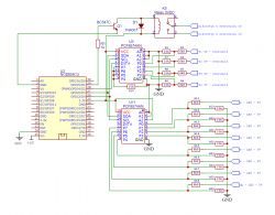
    Could you please elaborate because I don't think I quite understand how it works, the connection is supposed to be like this : ESP8266, PCF8574 and 7-segment LED how to connect it correctly?


    At least for now I'll do on the dividers (although the one with the diodes also interests me but I haven't understood it yet), I'll order some voltage converters and maybe in the future I'll check how it works with them. I'm uploading the schematic of how I'm going to put it together for now (maybe I want to do something wrong), as the pushbutton operation is already there and tentatively working it's also on the schematic, I'll connect the PCFs on Friday or Saturday because tomorrow unfortunately I probably won't have time to play :) .
    ESP8266, PCF8574 and 7-segment LED how to connect it correctly?
  • #17 19262124
    krzbor
    Level 27  
    The I2C on the ESP8266 is implemented in software and does not sin the speed. It would be useful to use an oscilloscope or logic state analyser and check how fast the individual digits of the display are "swept". The block diagram of the PCF indicates that the reading is 'latched' i.e. these 8 bits are read simultaneously - a good characteristic. However, when reading a second PCF the latch will be at a different time point. The solution may be to drop one PCF (the one that selects the digits) and connect directly to the ESP (with logic level conversion of course). Then you will immediately know which character is driven and maybe have time to read the state of the segments in the digit. If the refresh is fast, the ESP can get busy just checking the status of the display (all 4 digits) and only do other things once the packet of information is complete.
  • #18 19262202
    tos18
    Level 42  
    CiekawyŚwiata wrote:
    Could you please elaborate because I don't think I quite understand how it works, the connection is supposed to be like this :


    No - diode reverse.
    Rather some faster than rectifier e.g. 1N4148
  • #19 19262577
    khoam
    Level 42  
    krzbor wrote:
    I2C on the ESP8266 is software implemented and does not sin the speed. It would be useful to use an oscilloscope or logic state analyser and check how fast the individual digits of the display are being 'swept'. The block diagram of the PCF indicates that the reading is 'latched' i.e. these 8 bits are read simultaneously - a good feature. However, when reading a second PCF the latch will be at a different time point. The solution may be to dispense with one PCF (the one that selects the digits) and connect directly to the ESP (with logic level conversion of course).

    All this is true of what you have written. In my opinion, however, it is better to use an expander that communicates over SPI, e.g. MCP23S17 or MAX7317. There is an SPI hardware controller in the ESP8266 and it works quite well. As far as software support for I2C in the ESP8266 is concerned, it will be quite a success to achieve a real I2C speed of 50 kHz if this interface is supported by the Arduino Core. If one insists on using I2C, it is better to use an alternative library for the ESP8266: Link .
  • #20 19264022
    krzbor
    Level 27  
    So I was thinking that the simplest solution would be to use a simple multiplexer with 8 inputs. The switching times of such a multiplexer are measured in ns. There are still enough inputs in the ESP to implement this, and it will work extremely fast.
  • #21 19264270
    janek_wro
    Level 29  
    krzbor wrote:
    I was thinking that the simplest solution would be to use a simple multiplexer
    Or maybe a PI/SO register would be better? e.g. something like 74xx674, 16 bit at once. Choose the series so that the inputs are 5V tollerant. probably LV.
    The only disadvantage is that such a register will not report an interrupt. It has to be implemented outside of it.
    krzbor wrote:
    with 8 inputs
    only 8? I thought you had more read lines in there.
  • #22 19264346
    CiekawyŚwiata
    Level 4  
    tos18 wrote:
    .
    There is also option 4 - diodes (12 pcs) facing anodes to the PCF.
    The PCF has a built-in input pull-up so you can power the PCF from 3.3V. A voltage higher than this the diodes won't let through (they will be in the negative) and when the tested atmega output is zero it will pull the voltage from the PCF leg through the diode
    .
    Are you sure the PCF has a pull up built in? I've searched and read but can't find anything conclusive even in the datasheet

    khoam wrote:
    krzbor wrote:
    I2C on the ESP8266 is implemented software-wise and does not sin the speed. It would be useful to use an oscilloscope or logic state analyser and check how fast the individual digits of the display are being "swept". The block diagram of the PCF indicates that the reading is 'latched' i.e. these 8 bits are read simultaneously - a good feature. However, when reading a second PCF the latch will be at a different time point. The solution may be to drop one PCF (the one that selects the digits) and connect directly to the ESP (with logic level conversion of course).

    All this is true of what you have written. In my opinion, however, it is better to use an expander that communicates over SPI, e.g. MCP23S17 or MAX7317. There is an SPI hardware controller in the ESP8266 and it works quite well. As far as software support for I2C in the ESP8266 is concerned, it will be quite a success to achieve a real I2C speed of 50 kHz if this interface is supported by the Arduino Core. If one insists on using I2C, it is better to use an alternative library for ESP8266: Link
    .
    I've ordered some from eastern neighbours if it doesn't work after I2C then there will be something else to work on :)
    Thanks for the library maybe I can still test today.

    janek_wro wrote:
    krzbor wrote:
    I was thinking that the simplest solution would be to use a regular multiplexer
    Or maybe a PI/SO register would be better? e.g. something like 74xx674, 16 bit at once. Choose the series so that the inputs are 5V tollerant. probably LV.
    The only disadvantage is that such a register will not report an interrupt. It has to be implemented outside of it.
    .
    Are you referring to, for example, the HD74HC674? Any example usage for a similar application, from the datasheet I didn't find out/understand much.
  • #23 19264635
    janek_wro
    Level 29  
    CiekawyŚwiata wrote:
    Are you referring to, for example, the HD74HC674?
    .
    Oj I don't know if the HCs don't have a diode on the input to Vcc. If so, it won't take 5V well at the input, with Vcc=3.3V.

    In the TI documentation I found:

    Overvoltage-Tolerant Devices
    Devices with overvoltage-tolerant inputs
    can be used to perform down-translation.
    Logic families with overvoltage-tolerant
    inputs include:
    • AHC
    • AUC
    • AVC
    • LV-A
    • LVC

    CiekawyŚwiata wrote:
    Some example use in a similar application, from the data sheet I didn't find out/understand too much.

    https://en.wikipedia.org/wiki/Shift_register#Parallel-in_serial-out_(PISO)
    there you have an illustrative picture.

    Example use - what you need. You latch in parallel, all bits at the same time, and then eject to the output one bit at a time, in rhythm with the given CLK.
  • #24 19264647
    CiekawyŚwiata
    Level 4  
    janek_wro wrote:
    CiekawyŚwiata wrote:
    Is this about the HD74HC674, for example?
    .
    Oj I don't know if the HCs don't have a diode on the input to Vcc. If so, it won't take 5V well at the input, with Vcc=3.3V.

    In the TI documentation I found:

    Overvoltage-Tolerant Devices
    Devices with overvoltage-tolerant inputs
    can be used to perform down-translation.
    Logic families with overvoltage-tolerant
    inputs include:
    • AHC
    • AUC
    • AVC
    • LV-A
    • LVC
    This is probably already too high a threshold for fox legs.... I'm still not able to figure out what specific circuit this might be about. I'm looking for 74AHC674, 74LV-A674, 74LV674 - something's not right here, probably not the way to go.... I'm probably too stupid for this ;)

    janek_wro wrote:
    CiekawyŚwiata wrote:
    Some example use for a similar application, from the data sheet I didn't find out/understand much.

    https://en.wikipedia.org/wiki/Shift_register#Parallel-in_serial-out_(PISO)
    there you have an illustrative picture.
    Example use - what you need. You latch in parallel, all bits at the same time, and then eject to the output one bit at a time, in rhythm with the given CLK.

    I understand correctly that the main difference (or not the main difference) is that no interface in the sense of I2C or SPI is needed to support the 74xx674?
  • #25 19265186
    mpier
    Level 29  
    Going back to the ESP32-CAM for a moment:
    CiekawyŚwiata wrote:
    One can go either way but I don't like this way, how to approach such a boiler afterwards? :/
    .
    E.g. like this: tup, tup, tup. Have you seen the dimensions of this camera?
    CiekawyŚwiata wrote:
    Do I understand that the basic difference (or not basic) is that no interface in the sense of I2C or SPI is needed to support the 74xx674?
    .
    Every chip needs some kind of "interface".
    Maybe use a cheap atmega328p in tqfp32 instead of those registers. If you bend the legs well you can do without soldering, and stick the chip on thicker double-sided tape.
    Take into account the risk of damaging the original microcontroller.
  • #26 19265230
    CiekawyŚwiata
    Level 4  
    CiekawyŚwiata wrote:
    tos18 wrote:
    .
    There is also option 4 - diodes (12 pcs) facing anodes to the PCF.
    The PCF has a built-in input pull-up so you can power the PCF from 3.3V. A voltage higher than this the diodes will not pass through (they will be in the negative) and when the tested atmega output is zero it will pull the voltage from the PCF leg through the diode
    .
    Are you sure the PCF has a pull up built in? I have searched and read but have not found anything conclusive even in the data sheet
    .
    Theoretically the best thing to do would be to plug in the PCF and see how it works, which is what I did but I'm not sure of the interpretation of the results :) .
    Whether I set INPUT or INPUT_PULLUP the program behaves exactly the same, if I don't put anything on P1 it is always HIGH, if I connect to GND it is LOW, if I connect to power it is HIGH. If I understand this correctly, when declaring it as INPUT (without PULLUP), if I don't specify anything, the value may float, but I didn't observe anything like that. I found somewhere that you can use digitalWrite(pin, LOW/HIGH) to turn PULLUP on or off but that didn't change anything either, pity there is no PULLDOWN.
    Below is the code I used for testing, the library I used is: PCF8574_library .

    Code: C / C++
    Log in, to see the code
    .

    Added after 8 [minutes]:

    mpier wrote:
    Back to the ESP32-CAM for a moment:
    CiekawyŚwiata wrote:
    You can go either way but I don't like this way, how to approach such a boiler later? :/
    .
    E.g. like this: tup, tup, tup. Have you seen the dimensions of this camera?
    .
    it's not the camera I'm worried about but the servo for the button
    mpier wrote:
    CiekawyŚwiata wrote:
    Do I understand that the basic difference (or not the basic difference) is that no interface in the sense of I2C or SPI is needed to operate the 74xx674?
    .
    Every chip needs some kind of "interface".

    Maybe I'm not using technical terms properly, I meant more that some circuits communicate via I2C others via SPI, RS485 etc. and some I connect to analog or digital inputs and simply read the voltage (in the case of analog) or the high/low state, this is certainly some way of communication but I don't think it can be called an interface, or maybe I'm wrong?
    mpier wrote:
    Take the risk of damaging the original microcontroller.
    risk included, before I started playing around I checked that I could buy the same for 100-150zl and decided that I could safely bear such consequences in case of failure (of course I made a copy of the controller settings I have installed).
  • #27 19265293
    krzbor
    Level 27  
    Maybe to start with, connect the digit selection through the divider to the ESP leads. You'll be able to see if anything is changing (scanning the digits). With the timing functions on the ESP you will also determine how fast the subsequent digits are being swept. Note that you cannot connect to the base of the transistor - the voltage there changes between 0V and 0.6V. You must connect in front of the base current-limiting resistor (which is basically the microprocessor leads).
  • #28 19265308
    khoam
    Level 42  
    CiekawyŚwiata wrote:
    I found somewhere that you can use digitalWrite(pin, LOW/HIGH) to turn PULLUP on or off but that didn't change anything either, too bad there is no PULLDOWN.
    .
    Then do an external pull-down - 100k resistor to ground on the input and INPUT mode. However, digitalWrite() is definitely not for pull-up on/off.

    Added after 13 [minutes]:

    CiekawyŚwiata wrote:
    maybe I'm not using technical terms properly, I meant more that some circuits communicate over I2C others over SPI, RS485 etc and some I connect to analogue or digital inputs and simply read the voltage (in the case of analogue) or the high/low state this is certainly some way of communicating but I don't think it can be called an interface, or maybe I'm wrong?
    .
    A question of semantics. The latter case could be called a software interface ;) .
  • #29 19265631
    CiekawyŚwiata
    Level 4  
    The topic has stretched a bit and I have another question related to a project I am working on. At the moment I'm using a relay to short-circuit a microstick and can this be solved with some dimensionally smaller components? Electronic/digital relay? Transistor, optocoupler?
  • #30 19265784
    tos18
    Level 42  
    You need to look at how the microsticks are connected - do they short circuit the line to ground or something else. Try to draw it.
    Usually a single transistor is enough.

Topic summary

The discussion revolves around connecting an ESP8266 (NodeMCU V3) with a PCF8574 to read the status of 7-segment LEDs from another device. Users explore the voltage requirements of the PCF8574 and the LED specifications, particularly the KT10521BJ1B model, which lacks a datasheet. Various methods for interfacing the PCF8574 with the LEDs are proposed, including using resistors, multiplexing, and level shifting. The importance of handling interrupts for efficient reading of the LED states is emphasized, along with suggestions for using alternative components like SPI expanders (MCP23S17, MAX7317) and shift registers (74HC165). The conversation also touches on practical implementation challenges, such as voltage levels, debounce handling for buttons, and the potential for using simpler components like transistors or optocouplers for circuit control.
Summary generated by the language model.
ADVERTISEMENT