Hello my dears
I will show here how you can easily assemble your own IoT WiFi controller from ready-made modules (ESP8266, power supply, relay). In the example version, it will allow us to turn on/off one device via the Internet. It will be like a Sonoff DIY version, with a detailed description of the next steps. For the project I will use ready, free Tasmota firmware for ESP. In addition, I will also present how you can conveniently control Tasmota devices from a free phone application (without the use of an intermediary / broker).
The theme, of course, is intended for slightly less advanced users. Rather, experienced here will not learn much.
Entry
Of course, the Sonoff itself does not make sense to make it yourself, because it can be easily purchased. But the method shown here is universal, it allows you to make any WiFi-controlled layout. A lot can be done without recompiling the Tasmota firmware (this soft allows you to set what is on which ESP pins via the website), and even more possibilities open up when you are ready to do your own firmware compilation and know a bit of the C language.
In the same way, you can also transfer any ready-made 'smart home' device based on ESP8266 (e.g. from Blitzwolf) to Tasmota and use it normally with open source software, free from the intermediation of the manufacturer's cloud. Some often have various allegations that the manufacturer can, for example, track and save user activities, and the process from the subject excludes this risk.
Modules used
I used easy to buy modules for the project.
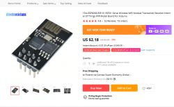
First of all, the WiFi module, i.e. the board with ESP8266, here ESP8266-01 . Some photos from the auction:
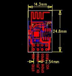
Leads:
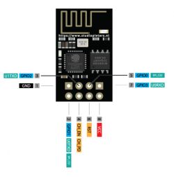
NOTE: ESP8266 is powered from 3.3V. 5V voltage will damage it!
5V power supply. The smaller the better, but it must provide sufficient current for the ESP and for what we want to connect. Current measurements at 5V for ESP8266-01 and one relay are placed at the end of the topic.

parameters:
Quote:
Input voltage AC85~265v 50/60HZ
Output voltage DC5V
Operating current 500mA Dimensions
Volume: LWH 32*18*13(mm)
Photos:
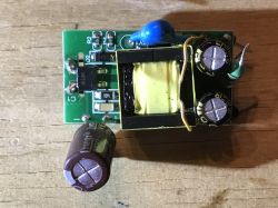
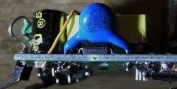
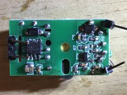
The power supply above is of course a flyback switching power supply, based on the AP8012 chip, on the secondary side there is also a TL431 (i.e. a precise reference voltage source), under the large capacitor connecting the secondary side with the primary side there is an optocoupler. At the output, this power supply has two electrolytic capacitors and a choke, which together form a filter, but there is no fuse at the input, so one should also be supplied loose. I chose the fuse from an old 5V power supply of similar power.
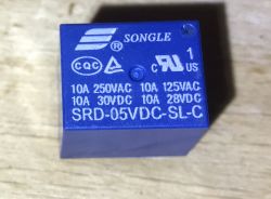
5V relay The SRD-05VDC-SL-C is very popular:

Internal diagram, pins:
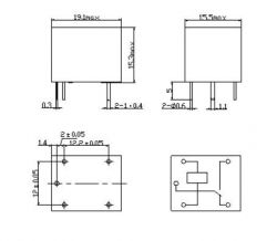
Photo:
Additionally:
- some USB to UART converter to upload the batch to ESP (or ESP to USB 'programmer')
- 3.3V LDO regulator, for ESP power supply. I had the MCP1702 on hand, and I regularly use the TC1264
- Transistor (to turn on the relay). I used BC547
- The diode that is connected in parallel to the relay winding can be 1N4148
- Button
- Few capacitors (100nF before LDO, 100nF after LDO, some electrolytic after LDO)
- goldpin 4x2 socket for ESP and additionally better also for the power supply (so that it can be easily removed)
- Small items (resistors, jumpers)
Below, I'll walk you through the step-by-step procedure for assembling your own Sonoff.
Step 1 - ESP8266 programming
First you need to upload the appropriate soft on the ESP8266. You can do it with any USB/UART adapter HW-597:
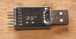
This adapter supports the 3.3V UART logic level required by ESP8266; in order to set it, you need to put a jumper on the VCC and 3.3V pins; however, we cannot power the ESP8266 from the 3.3V pin there because it has too low current efficiency, you need to connect the 3.3V LDO regulator to 5V from USB (it is also derived on the adapter). In addition, we need 10k resistors on RST and CH\PD. Details below:
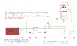
(it is worth knowing that, for example, in the case of another module with ESP, e.g. something from Tuya, you may need to put a pull-up resistor on IO0, but the board used in this topic already has this resistor on it, so I did not put it on the diagram )
I made these connections on the breadboard:
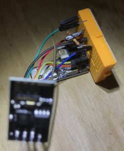
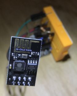
First, I checked the operation of AT commands. Firmware from AT is loaded by default on this module with ESP, but of course it will not work if we overwrite it. No need to short IO0 to test AT.
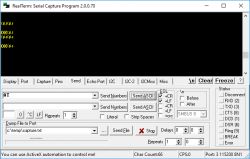
After sending the "AT" command, the module replied "OK", so the communication is working.
Then it was time to upload Tasmota's input. Download from here:
http://ota.tasmota.com/tasmota/release/
On the computer side I used esptool.py installed with the Arduino IDE ESP support package:
https://github.com/esp8266/Arduino
I installed it via Boards Manager.
The programming procedure here is as follows:
- disconnect everything from the power supply (remove the plug from the USB port)
- short the GPIO0 pin to ground
- reconnect the power supply
- wait a few seconds
- disconnect GPIO0 from ground
- start esptool
Of course, instead of cutting off the power supply, you can simply use the RESET pin, but I prefer to describe the method without using the RESET pin because some ready-made smart modules/devices, e.g. from Tuya, do not have the RESET pin led out, so this method is more universal.
At the beginning, the communication check itself - the command esptool.py chip_id . It should correctly detect the COM port itself and then the ESP module, its MAC, etc.
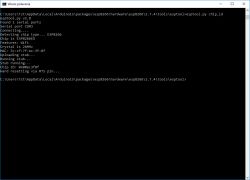
If everything is ok, you can now program. Command esptool.py write_flash 0x0 tasmota.bin (I put the .bin file in the same folder as esptool).
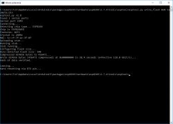
Since then ESP has Tasmota's flash loaded (and will no longer support AT commands, AT flash has been overwritten)
Step 2 - configuring Tasmota - WiFi configuration
After restarting the module (remember to disconnect GPIO0 from the ground), the Tasmota WiFi network should appear:
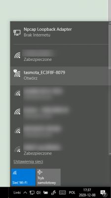
After connecting to this network, you can start configuring Tasmota, i.e. give the device the location of our WiFi. The device is always available on IP 192.168.4.1 (of course only temporarily, then it will get its IP via DHCP from our router):
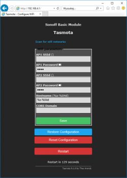
Here we also set the hostname of our device (hostname) which we can use to recognize it instead of the IP address.
We save the changes:
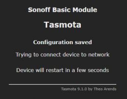
At this point, the WiFi network from Tasmota should disappear. However, our router should detect a new device.
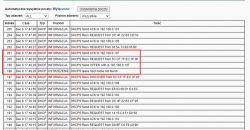
192.168.0.107 is the IP assigned to ESP via DHCP by our router. This IP is variable, it may change in the future. The message "lease host name not found" means that my router does not support setting the client's hostname, it is not necessary, although it could be useful if, for example, we were using an IP scanner to determine what devices we have connected.
Step 3 - configuring Tasmota - configuration of output pins
From now on, the device is available in our WiFi network at the address 192.168.0.107. There you can specify what is connected to which ESP pin and how it is controlled:
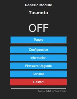
We open Configuration:
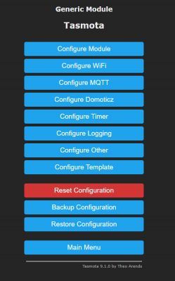
Then Configure Module:
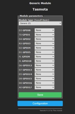
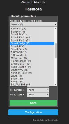
We can do two things here. You can set a specific type of board we have (this limits the number of available pins):
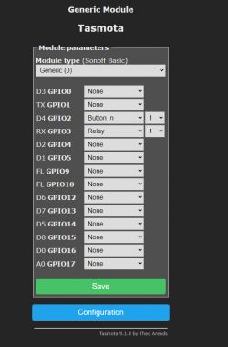
We can also set the role of specific pins (and there are many roles, everything is ready to use):
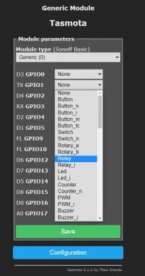
We can set a different number of relays (you just choose their index) and Tasmota will create buttons for them on the website itself, physical buttons from the system will also connect to them (by index).
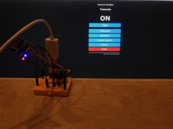
The system made in this way works - the state of the LED can be changed both with the button and through the website. After changing the status of the LED with the button, the page refreshes itself after a while:
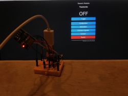
Step 4 - the rest of the layout
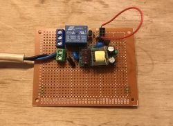
It's up to the creativity of the user. You can etch the PCB yourself, you can order it from a tile shop, you can solder the whole thing on a universal drilled plate. The setup is simple, shouldn't be a problem. You just need to remember to keep the right distance between the paths connected to the network and the rest of the system. In the case of a drilled plate, it is worth removing the copper eyelets between them at all (pressing them lightly with the soldering tip will make them fall off). It is also worth using the sockets for the power supply module and ESP8266, to be able to remove them if necessary, e.g. to update the firmware (although it can also be done via WiFi).
Wiring diagram:
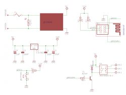
In principle, everything is the same as in Sonoff, so it is also worth getting acquainted with its scheme:
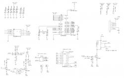
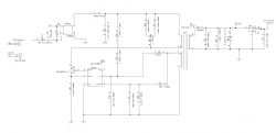
There are also two voltages in Sonoff, 5V for the relay and 3.3V for the ESP. The relay is controlled by 2N7002.
Tasmota's final configuration:
During submission:
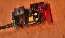
Almost ready:
Step 5 - housing
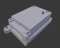
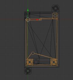
There are life-threatening voltages in the system, so it is even more important to think about the housing. I designed my case in Blender and printed it from PLA filament on the Ender 3 Pro 3D printer. Case design:
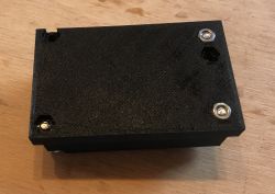
Folding:

Complex relay:
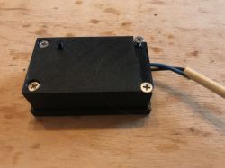
The housing consists of four parts:
- base
- cover
- additional cover for screw terminals
- button (actually it's an "extension" that presses the tactile switch button)
Step 6 - Static IP
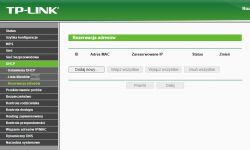
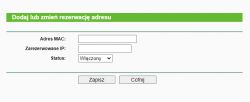
There is still the issue of the IP address of the device. By default, it is dynamically assigned by the router via DHCP, so it may change. It is not always what we expect.
Fortunately, Tasmota can be given a static IP, i.e. one that does not change.
This is done in the Tasmota console:

We enter there: IPAddress 192.168.0.50
The following response should appear in the console:
Quote:
13:19:26 CMD:IPAddress 192.168.0.50
13:19:26 RSL: stat/tasmota_EC3F8F/RESULT = {"IPAddress1":"192.168.0.50 (192.168.0.107)"}
Then you need to restart the device:
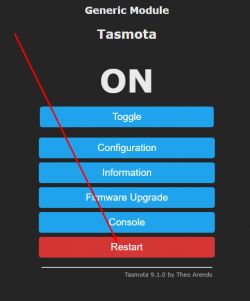
From then on, the device will always have this IP address. If we were using MQTT and a broker, it wouldn't be needed, but here I show how to do without it.
Step 7 - Phone application
Normally, you would still need to put your MQTT broker, i.e. an intermediary between our phone and Tasmota devices, but to some extent it can be omitted.
There are applications that allow you to directly control Tasmota devices.
They differ from Blitzwolf, Smart Life, and other companies' applications primarily in that they do not require a connection to the manufacturer's server, i.e. they do not track, do not collect data, and we have control over everything.
(Although in an ideal scenario, we should compile such an application ourselves from the source code, and not download it from, for example, Google Play).
An example of such an application can be Tasmota Control:
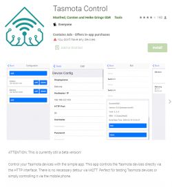
NOTE: DHCP on the router does not guarantee that the same device will always get the same IP. If we want to use this app in the long run, we need to configure it to have a static IP. Otherwise, you will pair the app with the device, and then a few days (or months) will pass and suddenly the device's IP will change to a different one ... an alternative solution is to refer to the device by its hostname. It can be used instead of an IP address.
After starting Tasmota Control, we have three buttons to choose from:
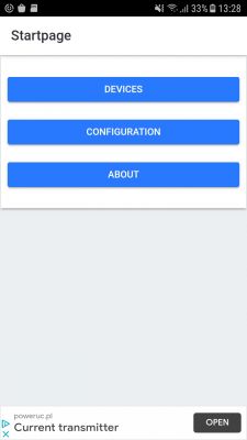
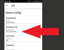
In Configuration, we add a new device. It only comes down to entering its IP address (and port 80, as communication takes place over HTTP). Nothing else is needed:
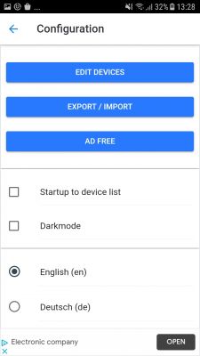
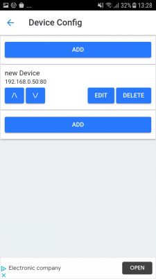
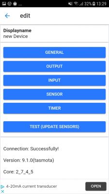
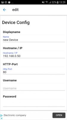
The interface here is a bit strange, because first we have to click "Add", then find the just added device on the list, click "Edit" and there in "General" set the IP. But it's a beta version.
From now on, in Devices we have a new device:
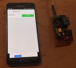
And we can control it over the phone, of course, without the intermediation of third parties (without external companies that can collect data about us) and without the need to connect to the Internet, all within our one WiFi.
Step 8 - presentation
The video below shows the operation of the complex relay, along with its website for control (the one based on ESP) and the Tasmota Control application. You can see how quickly the relay reacts to the button and how quickly the applications show its new state:
It is worth noting here how it works internally. Applications here must constantly ask ESP about its state, they use the HTTP protocol, and more specifically queries like:
http://192.168.0.50/cm?cmnd=Status%200
The same can be sent via the browser and see what Tasmota responds. Tasmota's response:

This response is in JSON format.
In the same way, applications control the relay. They send the command via HTTP:
http://192.168.0.50/cm?cmnd=Power%20TOGGLE
ESP responds to this:
{"POWER":"ON"}
Of course, we also have MQTT, but it is not used here.
In addition, there is one conclusion - the open application (or website) actively queries the ESP about its state. It is the application that establishes the connection (as a client) and ESP only responds.
Measurement of voltage, current
I also measured how much current the circuit presented here draws, separately with the relay on and off.
I made the measurement at the output of the 5V power supply (i.e. losses on it are not included), i.e. before the 3.3V MCP1702 regulator used.
The output is stable 5V, even under load:
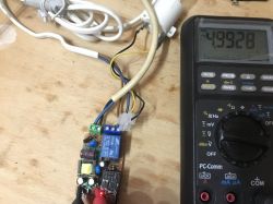
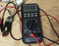
Then power consumption. With Relay ON:
With off:
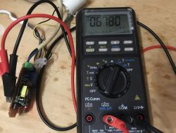
The current consumption varies a bit depending on whether the ESP is transmitting. In the photos above are the largest recorded measurements I had, sometimes they were also lower. During the measurements, the ESP was connected to my WiFi network and I had its website open (i.e. ESP communicated on an ongoing basis and must have been broadcasting, because both the website and the phone application constantly query ESP about its status).
I noticed that when the ESP is not transmitting at all, the current consumption drops from the 60mA shown to even 20mA.
In summary, with ESP network activity we have:
- with the relay switched on until 140mA at 5V, which is 0.7W (+ power supply losses)
- with the relay switched off until 70mA at 5V, which is 0.35W (+ power supply losses)
When ESP is not transmitting, power consumption drops. ESP isn't transmitting all the time, so it's probably basically using less than that 0.7W.
The results of my measurements are consistent with the measurements for the classic Sonoff that I found on the web.
Tip: How does Tasmota's page refresh work?
We can also see how the refresh of the website of the Tasmota device is performed. To do this, we will view its source by typing in the browser:
view-source:http://192.168.0.50/?
In this way, you can view the HTML code of any website we visit.
Tasmota's website code looks like this:
[syntax=html]
Tasmota - Main Menu
var x = null,
lt, to, tp, pc = '';
function eb(s) {
return document.getElementById(s);
}
function qs(s) {
return document.querySelector(s);
}
function sp(i) {
eb(i).type = (eb(i).type === 'text' ? 'password' : 'text');
}
function wl(f) {
window.addEventListener('load', f);
}
function la(p) {
var a = '';
if (la.arguments.length == 1) {
a = p;
clearTimeout(lt);
}
if (x != null) {
x.abort();
}
x = new XMLHttpRequest();
x.onreadystatechange = function() {
if (x.readyState == 4 && x.status == 200) {
var s = x.responseText.replace(/{t}/g, "").replace(/{s}/g, "").replace(/{m}/g, "").replace(/{e}/g, "").replace(/{c}/g, "%'>
Cool? Ranking DIY Helpful post? Buy me a coffee.


