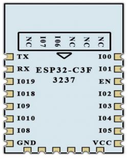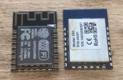
Hello.
Here I will describe the step-by-step process of replacing the WiFi module from a smart device. We usually do this replacement when we want to remove the WiFi module from the inside, which we are not able to program and replace it with something more popular, e.g. a module based on ESP. This allows us to ultimately use the selected open source firmware (eg Tasmota) and thus expand the capabilities of our device, as well as make it independent of the manufacturer's servers.
The process described here is commonly called "ESP8266 brain transplant" and you can find information about it on the web under this slogan.
NOTE: Hot air will be useful for the process and it may scare some people away, although I think that it is quite simple, I did it the first time and I do not have much experience with hot air.
Action plan
The adventure begins when we buy a Smart device which, unfortunately, does not have ESP inside, for example, has WB2S or XR3, and yet we want to upload Tasmota or a similar ESP firmware on it. Then we have to follow these steps:
1. compare the pinout of the module with the inside and check if a given ESP module (for example, ESP12F) can replace it
2. if the pinout is correct, desolder the module from inside
3. program the ESP module (loose or after soldering)
4. solder the ESP module in the place of the module
5. make any corrections to the system (soldering resistors necessary for ESP, or transferring the function to other pins)
6. ESP configuration with new firmware (here I will do it on the example of Tasmota)
NOTE: I will try to make the description of the process universal, so even if you have a different device than mine, the information provided here should be helpful.
Purchase of a door opening sensor
I found the sensor on the Internet under the slogan "Smart Wifi Door Window Sensor Burglar Security Alarm For Alexa Google Tuya" for less than $ 10, or PLN 40:

At the time of purchase, I did not know that the XR809 / XR3 was sitting there instead of the usual ESP.
I devoted a separate topic to this sensor:
WiFi door / window opening sensor - test, interior, integration with other devices
I also managed to make my own firmware for it, compatible with Home Assistant, but this topic describes the process of replacing the WiFi module, not creating the firmware, so we will assume that we do not have this firmware (or for some reason we want to specifically upload ESP firmware to it):
Proprietary open firmware for XR809 compatible with Tasmota HTTP / Home Assistant
After opening this sensor, I realized that it was XR3 inside:
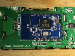
Information about the XR3:
https://developer.tuya.com/en/docs/iot/xr3-datasheet?id=K98s9168qi49g
The XR3 leads remind me of the ESP12F. There is a candidate for a substitution.
XR3 vs ESP12F
We already have a smart device with the XR3 / XR809 module and we have a potential replacement, ESP12F. It is also worth comparing their outputs carefully to see if the roles of the pins match.
Comparison:
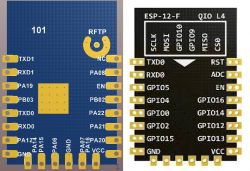
In XR3 we have an additional GND pin, which will shorten GPIO9 to ground. In XR3 we have NC (not connected) pin, in ESP12F there is RST. The location of TXD / RXD is a bit different, but that's not a problem. In addition, ESP12F will probably need to solder resistors that the XR did not require:

We will boot with SPI Flash, so you can see where you will need to solder resistors for this ESP12F ...
If we replace the unknown module in the Smart device with ESP and this ESP does not turn on, it is not worth getting discouraged, but you need to check in the catalog note whether all the requirements are met.
Purchase of ESP12F
ESP12F is very popular on the Internet and can be purchased from many stores. I probably bought my ESP12F here:

As far as I know, there are both original such modules and their counterfeits on the market, but at the moment I do not know if they have any significant difference from the topic to this application.
XR3 module outlet
First, we need to desolder the unwanted WiFi module from the device. In this case it will be XR3 / XR809, although there are also WB3S, WB2S and others (TYWE2S, TYWE3S do not have to be desoldered, because they are based on ESP).
Rather, it cannot be easily done with a simple soldering iron, although I have heard about methods of making a heated wire into a shape to match the pins ... but let's not complicate it.
For desoldering, I used cheap hot air with quite poor temperature control and a fairly large amount of flux. I chose the small diameter tip and gradually heated the rows of pads in turn.
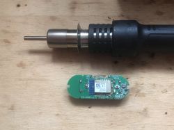
It is very important not to use force when desoldering. The module is supposed to "float", it cannot be pulled upwards, because then we will probably tear off the pads sooner and there will be a problem with soldering the replacement.
Of course, it is also important not to lose the module, but my subjective impression is that it is much easier to damage the pads than to overheat something.
Desoldered:
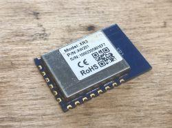
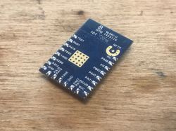
Tile without module, quite unusual sight. All pads are complete:
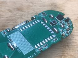
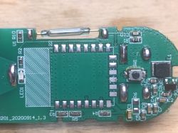
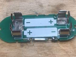
At this stage, I recommend you to follow all the paths and take good quality photos, because then when the ESP module is soldered in place, it will be hard.
Comparison of both modules
We will take this opportunity and compare both modules visually. Haven't seen the XR3 from below yet. Both have signed pads. At first glance, the conclusions are compatible.
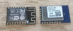

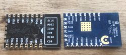
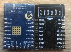
Programming ESP12F in bulk
Now we have two options. Shell we:
- or immediately solder the ESP module to our Smart device, and then program it (then connect to the UART)
- or program the ESP first, and then solder it to the Smart device
I chose the latter option because I wanted to make sure that everything was working before soldering the module to the board.
I have already described ESP programming several times, incl. here:
- https://www.elektroda.pl/rtvforum/topic3749207.html
- https://www.elektroda.pl/rtvforum/topic3736876.html
- https://www.elektroda.pl/rtvforum/topic3760371.html
This time I used a slightly different USB-UART converter:

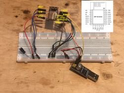
From it, I only used RX, TX, + 3.3V and GND. I did the rest of the connections myself:
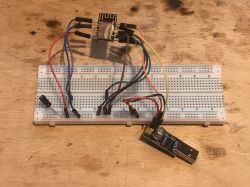
The same picture but with the roles of the pins:
To upload the batch on the computer side I used esptool.py which I installed with ESP8266 support for Arduino IDE. Below is an example of use, first the chip_id command to check if ESP is seen, then programming.
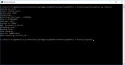
Program:
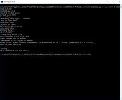
Then I disconnected the power and connected GPIO0 to VCC so that ESP started not in programming mode, but in normal operation and created a Tasmota access point confirming that everything is working:

So the ESP is definitely working, it's time to solder it.
First run after replacing XR809 with ESP12F
Before soldering, I cleaned the pads and smeared with flux and whitened. First, I tried to solder the module with hot air, but in the end I simply corrected every solder by hand with a soldering iron.
Unfortunately, the web did not appear. I had to check each pin with a multimeter. My suspicions are confirmed. You had to add a 10k pull up resistor for EN and GPIO0 and a pull down resistor for GPIO15. In addition, I had to remove the diode from GPIO15 (unfortunately they just gave it there and this diode forced a high state on this pin and started ESP booting from an SD card ...).
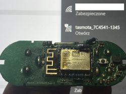
It was enough for ESP to come alive.
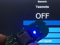
We activate the LED from the deck and the button
I moved the LED diode from the deck to the pin of my choice, I just added a jumper.
The button was on the GPIO13 pin.
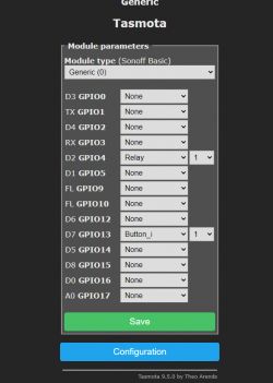
That was enough to control the LED via WWW:
A method for a sensor, i.e. Tasmota and pin digital input
Operation of the magnetic door opening / closing sensor is as simple as reading the pin in digital input mode. It should be easy on the surface, but we have two small problems to overcome.
First, Tasmota does not have a "Digital input" mode for the pin, we only have a Switch or Button and their status is not shown on Tasmota's GUI. This can be solved by adding an additional pin pretending to be Relay and giving it the same number as our Switch. This pin will not actually be connected anywhere, but then Tasmota's GUI will display this pseudo-Relay and thus show us the state of the Switch (because Switch and Relay with the same index are automatically connected in Tasmota).
So this configuration:
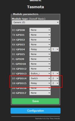
Secondly, however, that is not all. In the case of this XR809 door sensor, you still need to make a correction on the PCB, otherwise the Switch will be still high.
A brief analysis of the system shows that the magnetic sensor has a 10k pull up resistor and a 3M pull down resistor. GPIO is connected to the pull down. In the "open" state it is 2.2V and in the "closed" state it is 3.3V. So it's still high.
In my opinion, it worked in the XR3 because the XR3 can operate on voltages up to 5.5V, and the ESP, in turn, only on 3.3V.
So you need to replace this pull down resistor with some 10k, or simply replace or solder a second one to it so that the resultant resistance is in this area.
Sketch / diagram of the situation:
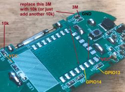
Soldered 10k:
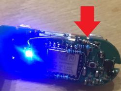
After this operation, the logical levels are normal. A change of state is immediately detected:
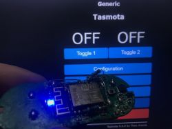
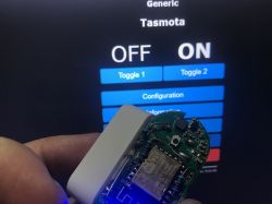
The first ON / OFF is the button temporarily assigned to the LED and the second ON / OFF is the door status (magnetic sensor).
Adding to Home Assistant
It is also worth showing what we can do with such a prepared door sensor in practice.
We will add it to the Home Assistant that I run on my own little home server.
I have described everything in detail here:
https://www.elektroda.pl/rtvforum/topic3777098.html
We add a door sensor via MQTT. MQTT configuration (but e.g. your password will certainly be different):
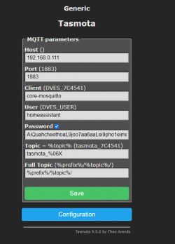
The sensor is immediately detected, although I do not know why as an "unknown device":

You can access information about this device. Here you can see a small problem - Home Assistant detects only one relay (one state) of the two, we will fix it in a moment.

Power 2 is not visible, but in MQTT it is (the window below is available under the "MQTT INFO" button):
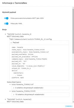
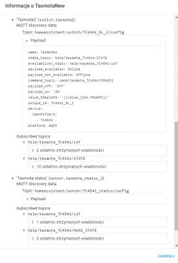
So MQTT sends the necessary information to the HA, on the HA side we just need to fix something.
Tasmota's documentation comes in handy:
https://tasmota.github.io/docs/Home-Assistant/
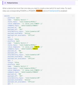
The paragraph "Multiple switches" tells how we need to modify the configuration:
My modified configuration.yaml (I added what is in the red box):
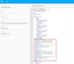
It is important to remember to set the device name. Here it is tasmota_7C4541. This name is available to us from the beginning, even Tasmota's open access point contains it, it is worth taking a note of it.
Code: text
In this way, I have both the Tasmota relay on the panel (both the one that is actually an LED and the one that only reads the door status):

You can enter their settings:

Rename them to something meaningful:
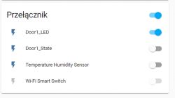
And above all, they can be used in automation.
Home Assistant - door status automation
At this stage, we have everything ready for automation. I have described them several times, so refer to related topics:
- Home Assistant Tutorial - configuration, WiFi, MQTT, Zigbee, Tasmota
- Relay driver compatible with Home Assistant / Tasmota HTTP + housing
We can now easily trigger events when, for example, opening the door and then automatically turn on the light in the room or send a notification. And Home Assistant ensures compatibility with a really large number of equipment from different manufacturers.
What else would you have to do?
There is basically one thing left to do to get the module 100% converted to ESP. There is still no reading of the battery status, which was performed on the XR3 via the ADC input. You could try porting this functionality to Tasmota, but for now I will stop here and temporarily recommend simply disconnect / cut off the appropriate path.
Summary
Replacing the XR3 module with the ESP12F was successful without any major problems. It is true that a few resistors had to be soldered, but after checking the ESP catalog note, it should be clear where they are added and for what purpose.
I also had to move the LED diode from GPIO15, because it happened there (it forced a high state on this pin and this blocked the activation of ESP).
The operation known in ESP societies as "esp brain transplant" is not that difficult at all, although you need to have this hot air to desolder the module relatively comfortably.
Of course, not only the XR3 / XR809 can be replaced like this. There are many other modules with compatible pins, you just have to look for. What's more, the Zigbee modules also have similar outputs, so replacing the device from Zigbee with ESP is also possible.
There is also the economic aspect of the entire exchange. For many devices, it definitely does not pay off. However, it does not mean that it is always like that. More expensive smart devices may not have ESP inside and not have identical ESP counterparts. For example, in the queue for conversion, I have an Alfawise P2 Hepa air filter, I will be checking it soon and if there is no ESP there, I will probably do a conversion.
Have you changed any Smart devices to use the ESP module and what is your experience with it?


