logo elektroda
logo elektroda
X
logo elektroda

DIY Wind Turbine Battery Charge Controller

Alpha 11919 13
ADVERTISEMENT
Treść została przetłumaczona polish » english Zobacz oryginalną wersję tematu
  • PCB schematic for a battery charging controller.
    Welcome.
    I would like to present you a simple controller for charging batteries from a small wind turbine, using a ready-made up / down converter module on the XL6009 chip.

    However, I must start with the fact that I have dreamed of having a small wind turbine for a long time. And although reading many statements on the Internet convinced that they do not meet the hopes placed in them, I was already determined to order something cheap on the Polish or Chinese auction portal and check it for myself.
    The turbine was to support a small solar system that charges 12V batteries and powers various crap ;) .
    Fortunately, at the last minute there was an opportunity to buy a used brand Rutland 910 turbine, which I used.
    Its parameters are:
    - rotor diameter 91cm
    -6 shovels
    - maximum power 80W
    -weight about 15 kg
    From myself I can add good balance, quiet operation and low rotation resistance.
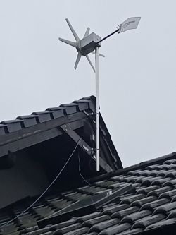
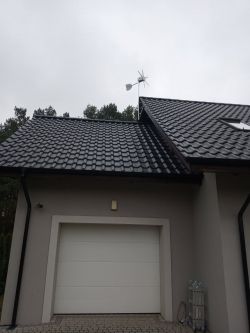
    The windmill was mounted on the top of the building, about 10m above the ground.
    Behind the building there is a forest wall, and the plot is located in a fairly large depression, but the windmill starts up surprisingly eagerly even with slight gusts of wind.
    However, concerns have been confirmed that the amount of voltage generated during the vast majority of operating time is too low to be used directly. Even - subjectively perceived - quite fast rotation of the blades, generated the output voltage in the range of 7..9V. Higher tension was extremely rare.
    However, I wanted to use at least some of the energy that is generated and hence the idea to use a converter that will increase or decrease the input voltage depending on the need.
    The structure was to be simple and made of easily accessible elements.
    I decided to use one of the ready-made modules available in many variants on the Chinese website and after reviewing them, the choice fell on the XL6009 chip. It meets all my assumptions: input voltage 3.5V-32V, current up to 3A and - what is very important - Enable input, which allows you to turn the inverter on and off.
    You can also use the module with the XL6019 chip, which has an additional soft-start function, but its efficiency is only 1.5A.
    However, converters with the LM2577 system are not suitable, because they do not have the Enable input mentioned above.
    It was only necessary to add a system that would activate the converter so that it would operate in a safe voltage range (above Umin.) And would not choke the turbine's rotation. The large capacitances of the capacitors at the input were to extend the converter operation cycles. The output voltage of the XL6009 was set to 14.5V.
    A system for detecting too high input voltage was also created immediately, which switched on the braking load in the form of a 50W bulb.
    And although the system worked and had considerable desulfating properties ( ;-) ), I did not like the continuous start-stop clocking of the converter (because supplying 14.5V voltage to discharged batteries with a large capacity caused a large current flow, which immediately discharged the input capacitors and the comparator turned off the converter).
    So I decided to make the output voltage from the converter dependent on the input voltage stored in the capacitors.
    This role is performed by one transistor that connects the feedback voltage wthe converter system: each increase in the input voltage causes a stronger control of the transistor, short-circuit of the RFB resistor, lowering the voltage at the FB XL6009 terminal, and thus increasing the output voltage by the converter, which aims to reach 1.25V at the FB terminal.
    As a result, the current flowing to the batteries increases with the speed of the wind blowing :) .
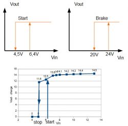
    Scheme and diagram of comparators and converter operation:
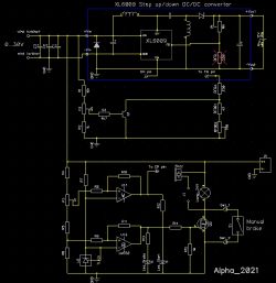
    Electrical schematic of a battery charging controller from a wind turbine using XL6009 Graphs showing the relationship between output voltage and input voltage in the charge controller.

    Item values are not critical and can be changed as needed.
    The small-signal NPN transistor used, with beta> 200, and the Mosfet-N with low parameters (200V, 0.3ohm), which I would not use anywhere else.
    My input capacitor bank has a total capacity of approx. 50mF, but it can be reduced.
    The maximum input voltage determines the applied LM324 and XL6009 and amounts to 32V.
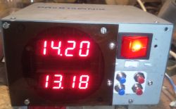
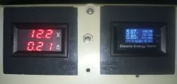
    I used two panel meters to visualize the parameters. A small note here: the Atorch 150V / 8A measuring combine used cannot be powered as shown in the diagram below, because part of the output current flows directly to the battery that supplies it, thus falsifying (lowering) the measurement made with the U / I meter.
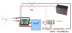
    Diagram of a simple battery charging controller from a wind turbine.
    The adjustment is best done by connecting the system to a regulated power supply.
    Set the voltage> 15V on the power supply, turn P2 fully to the left (to maximally drive the Q1 transistor base) and set the P1 multiturn potentiometer on the converter to the output voltage of 14.5-14.7V (max charging voltage, at your discretion). Reduce the supply voltage to the minimum, at which the converter does not turn off yet (about 6V), turn P2 to the right maximum, and P4 (Rfb2) set the voltage from which the converter will start to charge the battery after starting (less than 12V for me). Increase the supply voltage again to the level at which we would like to obtain the full charging voltage (i.e. 14.5V) and turn the P2 potentiometer counterclockwise until this voltage is obtained at the output.
    The P3 potentiometer can be used to set the thresholds at which the comparator will turn the converter on and off. The hysteresis is around 2V.
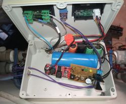
    I packed the whole thing into a plastic housing that had already been used in a similar project. I am not a special esthete, so don't judge me in terms of how the whole thing is finished. The voltage is low here, the currents are low - this will not burn my house ;) . It is a prototype and it will probably stay that way forever.
    When it blows, I will try to record a movie with the operation and indications of the meters.
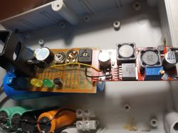
    Close-up of a converter module with XL6009 chipset in a plastic enclosure. Battery charging controller with XL6009 converter in plastic enclosure
    Finally, I would like to write a few words about the real gains from such a windmill.
    I do not have instruments for measuring wind speed, the location of the turbine is also very important, but during a windy day, when a person already feels a lot of discomfort during a walk, such a system, generating an average of about 2-5W, is able to cram about 11Ah into the batteries.
    Let me remind you - 24 hours of strong wind. It doesn't knock it down, does it? ;)
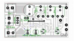
    I enclose the diagram and the pattern of the board ready for printing (after minor corrections - including replacement of the Q1 housing from Sot-23 to TO-92, and additional holes for smaller potentiometers). Project made in Dip-Trace.

    Cool? Ranking DIY
    About Author
    Alpha
    Level 26  
    Offline 
    Alpha wrote 1016 posts with rating 438, helped 58 times. Live in city Skoki. Been with us since 2003 year.
  • ADVERTISEMENT
  • #2 19698640
    gulson
    System Administrator
    Cool, would you have photos and a description of the turbine itself? Report to PW for an SD card :)
  • ADVERTISEMENT
  • #3 19698699
    khoam
    Level 42  
    A plus from me. I am interested in installing such a turbine - low power is not a problem, it is enough to illuminate the garden in winter. It blows quite regularly in my house. Could you write something more about the mounting of the FM910 turbine itself, with photos? The second question is whether there are any collisions between the turbine and the birds?
  • #4 19698749
    Alpha
    Level 26  
    The windmill is attached to the roof structure with an aluminum antenna mast and antenna / chimney grips. The whole thing is stable and has experienced many things.
    DIY Wind Turbine Battery Charge Controller DIY Wind Turbine Battery Charge Controller
    In the antenna mast, I had to increase (grind) the inner diameter a little, because the windmill mounting sleeve did not want to go there, but in the end it worked.
    It is not the cables that lay on the tiles, but the rope, which encouraged a bit of courage while climbing the roof structure ;) . I installed the handles this way and prepared the installation. However, I had to mount the turbine itself from the basket boom, which was a real acrobat with the weight of 15 kg on a 2-meter mast.
    I have not observed any effect on the birds, and I must admit that I was not indifferent to it. They still make nests within a short distance of the spinning blades, and they still enjoy singing :) . There were no accidents either.
    I also do not observe any transfer of vibrations caused by the rotating propeller to the roof / house structure.
  • ADVERTISEMENT
  • #5 19699257
    JohnKaldachar
    Level 7  
    Are such installations economically viable? Or is it rather a "flashing keychain"? Just such an unnecessary gadget.
  • #6 19699393
    Alpha
    Level 26  
    JohnKaldachar wrote:
    Are such installations economically viable? Or is it rather a "flashing keychain"? Just such an unnecessary gadget.

    Honestly - no, they don't.
    (Until recently - before subsidies and prosumers - photovoltaics was also like that.)
    It's just a hobby - it always costs money. But it also motivates to action, enjoys and teaches.
    I will not buy a shiny new car for it, because the old one is still driving, it is economical and failure-free. But it would be a "flashing trinket" ;)
  • #7 19699404
    actron
    Level 13  
    JohnKaldachar wrote:
    Are such installations economically viable? Or is it rather a "flashing keychain"? Just such an unnecessary gadget.


    Not necessarily, but sometimes it is a dream come true, pursuing a goal, achieving it, and most of all learning and a direction for further development.
  • #8 19699936
    george2002

    Level 21  
    You have to watch out for this converter because if the input voltage is lower than probably 3V, it gives 50V on the output ?? and only disconnecting the power supply "hangs" it ?
  • #9 19700148
    Alpha
    Level 26  
    george2002 wrote:
    You have to watch out for this converter because if the input voltage is lower than probably 3V, it gives 50V on the output ?? and only disconnecting the power supply "hangs" it ?

    I saw this thread once but forgot it was about the XL6009 - thanks for the reminder.
    At home, I did not notice any disturbing symptoms - due to the fact that the comparator watches over the converter's operation. Nevertheless, the point is correct - you have to be careful.
  • #10 19710102
    akajarz
    Level 23  
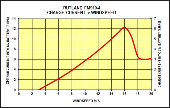
    According to the datasheet for this turbine, the power should be greater than these few watts, so there is something wrong. Either a damaged generator (maybe the diodes because it is a three-phase generator) or your converter does not load this generator sufficiently. Have you been looking with an oscilloscope what is the shape of the outgoing voltage?

    Graph showing charge current versus windspeed for the Rutland FM910-4 wind turbine.
  • #11 19715828
    Alpha
    Level 26  
    akajarz wrote:
    According to the datasheet for this turbine, the power should be greater than these few watts, so there is something wrong. Either a damaged generator (maybe the diodes because it is a three-phase generator) or your converter does not load this generator sufficiently. Have you been looking with an oscilloscope what is the shape of the outgoing voltage?

    Thanks @akajarz for your interest and this remark, I must admit that you sowed a seed of anxiety in me - I will have to climb up and check everything again.
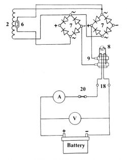
    My version is mkII, installation diagram below:
    Generator wiring diagram with component labels
    It does not look like a three-phase generator to me, but maybe I am wrong.
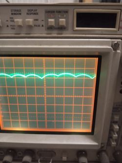
    Oscillogram from a generator loaded with a 100 ohm resistor, without filtering capacitors:
    Close-up of an oscilloscope display showing a sinusoidal wave and a measurement grid.
    It seems to me that with a damaged thermal fuse (which would probably be the most probable) and an open rectifier circuit, the voltage would be half-rectified and the oscillogram would look different.
    But it still cannot be ruled out that one of the diodes will be damaged ... I can only find out this by climbing the mountain with the meter.
    Photo and video of the converter operation:
    Two digital meters displaying voltage, current, and other electrical parameters.
    [movie: 9e5cf5d6fe] https://filmy.elektroda.pl/17_1637235491.mp4 [/ movie: 9e5cf5d6fe]
    The projected wind speed today is 23 km / h (approx. 6 m / s). Performance as seen in the video.
  • ADVERTISEMENT
  • #12 19715948
    tokrzych
    Level 16  
    Maybe such installations do not have an economic justification, but in the event of a power failure, they will always allow you to illuminate the house and charge your phone, which gives you psychological comfort. I live in a block of flats and I have a small panel in the window that powers my electronic LED clock and charges my phone with green energy. In the absence of tension, I can also illuminate the room
  • #13 19716159
    gulson
    System Administrator
    Exactly, nowadays people do not realize that even in a small apartment they should have a small maintenance-free battery with 7Ah charged or in buffer operation, to at least charge the phone and listen to radio messages, in the case of W.
  • #14 19722605
    Damian_Max
    Level 19  
    Cool design :D

    Do I understand correctly that over 12..20% of energy is emitted on rectifying diodes (those right behind the turbine)?
    -> We have a turbine (coil), it induces a current that is fed to the rectifier bridge, behind which there is a converter, i.e. the flowing current overcomes two rectifying diodes, i.e. some 2x0.7V = 1.4V, which divided by 7..9V gives the above estimate.
    If so, can it be optimized (?), For example, by using a H-bridge on some transistors with low forward voltage for rectification (I don't remember what it was, I only know that the same type + driver was used in the upper and lower branches) ?
    Or maybe there are such 'bridge rectifiers' on transistors with an integrated driver + driver ready?

Topic summary

A user presented a DIY battery charge controller for a small wind turbine utilizing an XL6009 up/down converter module. They shared their experience with a Rutland 910 turbine, detailing its specifications and installation on a roof structure. The discussion included inquiries about the turbine's mounting, potential bird collisions, and the economic viability of such installations. Responses highlighted the hobbyist nature of wind turbine projects, the importance of learning, and the psychological comfort provided by backup power systems. Concerns were raised regarding the converter's performance and the efficiency of the rectification process, with suggestions for optimization using low forward voltage transistors.
Summary generated by the language model.
ADVERTISEMENT