FAQ
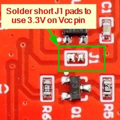
TL;DR: If your ESP32 + ILI9341 lights but stays blank, check power: 3.3 V logic and "the connector (pad) J1 on the display module should be shorted." One jumper fixes it. [Elektroda, khoam, post #19955843]
Why it matters: For ESP32 builders wiring ILI9341 modules, this solves blank/grey-screen issues and clarifies safe 3.3 V power selection.
Quick Facts
- For 3.3 V operation, short jumper J1 on the TFT breakout; it’s the power-select pad. [Elektroda, khoam, post #19955843]
- In this thread, a simple VCC-to-VIN solder bridge restored the display. [Elektroda, Atypowy256, post #19958571]
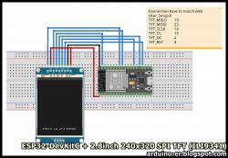
- Example VSPI wiring: SCK 18, MOSI 23, MISO 19, CS 5, DC 2, RST 4. [Techtutorialsx, 2021]
- ILI9341 SPI modules are QVGA 320×240; great for quick “Hello world” validation. [Techtutorialsx, 2021]
- Arduino IDE can compile fine while wiring is wrong. [Elektroda, Atypowy256, post #19954334]
How do I wire an ESP32 to an ILI9341 SPI display?
Use VSPI pins: SCK to GPIO18, MOSI to GPIO23, MISO to GPIO19. Choose free GPIOs for CS, DC, and RST (e.g., 5, 2, 4). Connect display VCC to 3.3 V and GND to GND. Keep wires short and twisted where possible. Load the tutorial’s example sketch to validate wiring. [Techtutorialsx, 2021]
My ILI9341 lights grey or shows a thin colored line. How do I fix it?
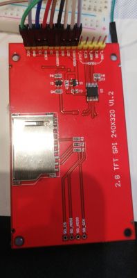
Fix the power selection. As one expert put it, “the connector (pad) J1 on the display module should be shorted.” Short J1 for 3.3 V operation, then power VCC from the ESP32’s 3.3 V rail. Recheck CS, DC, and RST assignments after the change. [Elektroda, khoam, post #19955843]
What exact fix worked in this Elektroda thread?
A solder bridge linking the display’s VCC and VIN pads, followed by powering from the ESP32’s 3.3 V pin, brought the screen to life. This simple change resolved the blank display despite a lit backlight. [Elektroda, Atypowy256, post #19958571]
Do I need to short a jumper to run the TFT from 3.3 V?
Yes. This board requires the J1 jumper closed for 3.3 V supply operation. After shorting J1, feed VCC with 3.3 V from the ESP32, and ensure GND is common. Verify your CS, DC, and RST pins in code. [Elektroda, khoam, post #19955843]
Which ESP32 pins should I start with for SPI?
Start with VSPI defaults: SCK 18, MISO 19, MOSI 23. Assign CS, DC, and RST to available GPIOs (e.g., 5, 2, 4). Update your library configuration to match these pins before uploading the example sketch. [Techtutorialsx, 2021]
What libraries and settings work on Arduino IDE?
Adafruit_ILI9341 with Adafruit_GFX or TFT_eSPI both work. Select the ILI9341 driver and define your CS, DC, and RST pins. The tutorial demonstrates a working pin map and “Hello world” code path for quick validation. [Techtutorialsx, 2021]
How can I quickly verify the display is alive?
Use this 3-step check: 1. Wire SCK 18, MOSI 23, MISO 19, plus CS, DC, RST as shown. 2. Power VCC from 3.3 V and share GND. 3. Upload the tutorial’s example; you should see 320×240 output with text and color fills. [Techtutorialsx, 2021]
Why does Arduino IDE show no errors even when the display shows nothing?
Compilation validates code syntax, not wiring or power selection. Your sketch can upload successfully while the display remains blank due to incorrect connections or jumper settings. Use a known-good example to separate software from hardware issues. [Elektroda, Atypowy256, post #19954334]
How should I connect the LED/backlight pin?
On the module discussed, LED and VCC were tied to the ESP32’s 3.3 V rail. Ensure the ground is common. If the board requires a power-select jumper, complete that first so the controller and backlight both receive correct power. [Elektroda, Atypowy256, post #19955837]
Should I connect VCC to VIN on my ILI9341 breakout?
Only if your board is designed for it via a solder bridge. In this case, linking VCC and VIN enabled proper 3.3 V operation and restored display output. Inspect the underside for labeled pads before bridging. [Elektroda, Atypowy256, post #19958571]
Do I need a common ground between ESP32 and the display?
Yes. Tie the ESP32 GND to the display GND to establish a reference for SPI signals. The example wiring in the tutorial shows a shared ground and stable operation using VSPI pins. [Techtutorialsx, 2021]
What does a grey screen with a thin colored line mean here?
In this thread, the symptom was reported as “glows grey and there is a thin line of the background colour I set.” It appeared before the successful power-jumper fix, indicating the software compiled but hardware needed adjustment. [Elektroda, Atypowy256, post #19955345]


