logo elektroda
logo elektroda
X
logo elektroda

How to Enter Flash Mode on ESP07 with DM-101 Board for ESPHome Upload?

mobopx 1359 10
ADVERTISEMENT
Treść została przetłumaczona polish » english Zobacz oryginalną wersję tematu
  • #1 19987462
    mobopx
    Level 11  
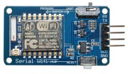
    Hello, I have an ESP-07 board on DM-101 Serial Wifi
    https://pl.aliexpress.com/item/32845872410.html
    onto which I am trying to upload ESPHome software using ESPHome Flasher.
    I am using a USB-UART converter (drivers installed, flasher correctly detects the converter on COM8). The error that comes up:

    Unexpected error: ESP Chip Auto-Detection failed: Failed to connect to Espressif device: No serial data received.

    My uncle said that you need to put the ESP into flash mode, but all the available ways that I have found involve a bare ESP board, some sort of PIN wipe etc. I haven't found info on how to enter flash mode on this particular version of the DM-101. will you direct me?

    I should add that I have no experience with AT commands. On the ESP I always uploaded ESPHome and continued to do the configuration there, but before that I had nodemcu type boards, so it was easier. This is where I unfortunately fell down....
  • ADVERTISEMENT
  • #2 19987473
    khoam
    Level 42  
    mobopx wrote:
    I couldn't find info on how to enter flash mode on this particular version of the DM-101.

    The switch named "SWITCH" :) It is drawn on the board how the ESP is to be set in programming mode, I mean left.

    How to Enter Flash Mode on ESP07 with DM-101 Board for ESPHome Upload?
  • #3 19987480
    mobopx
    Level 11  
    @khoam
    I'm already sitting on this for 3 hours :) switch I noticed right away, attempts were made on both PROGRAM and UART
  • ADVERTISEMENT
  • #4 19987484
    inot
    Level 37  
    Quote:
    the ESP is to be set to programming mode, i.e. left
    .
    It is important that already before the supply voltage is switched on.
  • #5 19987490
    khoam
    Level 42  
    @mobopx And how do you power this module?
  • #6 19987496
    mobopx
    Level 11  
    @khoam
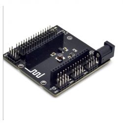
    12V power supply to base board from nodemcu, then power to ESP07 from 3.3V + GND pins. The LED on the ESP07 lights up red.
    How to Enter Flash Mode on ESP07 with DM-101 Board for ESPHome Upload? .
  • #7 19987516
    khoam
    Level 42  
    inot wrote:
    Quote:
    the ESP is to be set in programming mode, that means left
    .
    It is important that already before the supply voltage is switched on .
    .
    Not necessarily. It is important that the ESP is in programming mode before the firmware upload starts.
  • ADVERTISEMENT
  • #8 19987521
    inot
    Level 37  
    khoam wrote:
    Not necessarily. It is important that the ESP is in programming mode before you start uploading firmware.

    This is what I had in mind (due to the topic title) but now I see , that this connection error also occurs in UART mode.
  • #9 19987523
    mobopx
    Level 11  
    @khoam
    I'll also add that the converter works fine (I did a flash of ESPHome on ESP01 a while ago - it went without a stutter).

    When I switch to UART mode, ESP07 broadcasts its AP (ESP_xxx), but when I connect and enter ip 192.168.4.1 it shows that the page was not found.
  • #10 19987525
    khoam
    Level 42  
    Maybe they swapped the TX and RX pin descriptions?
  • ADVERTISEMENT
  • #11 19994512
    khoam
    Level 42  
    mobopx wrote:
    ESP07 flashes its AP (ESP_xxx), but after connecting and giving ip 194.168.4.1 it shows that the page was not found.

    If the ESP has not been previously "flashed" this is normal behaviour. Apart from the factory-set STA mode, IP address and WiFi network name, there is nothing else.

Topic summary

The discussion revolves around entering flash mode on an ESP-07 board mounted on a DM-101 Serial WiFi board for uploading ESPHome software using ESPHome Flasher. The user encountered an error indicating failure to connect to the Espressif device, attributed to the need for the ESP to be in programming mode before powering on. Participants suggested using a switch labeled "SWITCH" on the board to set the ESP in programming mode. It was emphasized that the ESP must be powered correctly, with 3.3V supplied to the ESP-07 while the base board receives 12V. The user also noted that the USB-UART converter was functioning properly, as they had successfully flashed another ESP device previously. However, issues persisted with the ESP-07 broadcasting its access point but failing to connect to the specified IP address.
Summary generated by the language model.
ADVERTISEMENT