logo elektroda
logo elektroda
X
logo elektroda
ADVERTISEMENT
  • The Nous Smart socket A1 contains a BK7231N and BL0942 power monitor. The BK7231N is soldered to one of the pcbs and is not on a separate module.

    Disassembly of the device is easy as there is a triangular screw under a paper label stuck onto the transparent plastic part of the socket.

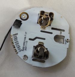
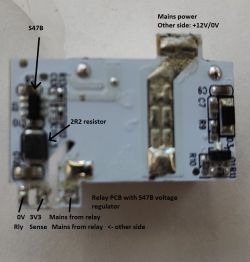
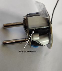
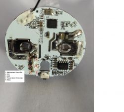
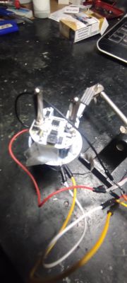
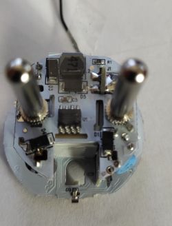
    Inside are 3 pcbs, one contains a switched mode 12V power supply, an intermediate board has the device relay and a S47B dc/dc power supply providing 3.3V to the top board that contains the BK7231N and BL0942.

    Flashing the chip is achieved using the python uploader

    Connections are as the same as described in the Qiachip Smart Switch - BK7231N / CB2S - interior, programming post with the exception of the 5V supply which is 3V3 from the 3V3 connection on the USB dongle.

    I also had to add a 10K pullup resistor from CEN to 3V3 and a switch to pull down to 0V to reset.

    Connections on the unit are:
    Relay: P26
    Switch: P9
    LED: P6

    There are mountings on the device for 3 leds although only D3 is mounted. The other leds are all wired in parallel.
    The BL0942 calibration program works correctly as described elsewhere.
    Nous Smart Socket A1 (BK7231)

    Nous Smart Socket A1 (BK7231)

    Nous Smart Socket A1 (BK7231)

    Nous Smart Socket A1 (BK7231)

    Nous Smart Socket A1 (BK7231)
    The power detect is the feed to the BL0942

    Cool? Ranking DIY
    About Author
    AcuarioCat
    Level 6  
    Offline 
    AcuarioCat wrote 8 posts with rating 10. Live in city Tortosa. Been with us since 2022 year.
  • ADVERTISEMENT
  • #2 20073906
    khoam
    Level 42  
    AcuarioCat wrote:
    Flashowanie chipa odbywa się za pomocą programu do przesyłania Pythona

    To tłumaczenie jest bez sensu.

    AcuarioCat wrote:
    Flashing the chip is achieved using the python uploader

    What kind of python uploader? The title of this article (in Polish) is about firmware updates, but there is hardly anything about it in the article itself.
  • ADVERTISEMENT
  • #3 20073989
    speedy9
    Helpful for users
    Doesn't it use OpenBK7231T developed by our colleague @p.kaczmarek2?
  • #4 20074329
    AcuarioCat
    Level 6  
    Yes it uses the firmware OpenBK7231T - in this case it's an N chip so uses the N SDK.
    I tried to post links but I can't as I don't have enough posts.
    Sorry, my Polish, like my Greek is zero.
    It would be better in the Teardowns section of the forum. I did try to post it there but the moderator moved it to the section where it is now.

    It is a detailed teardown of the smart socket with details of the gpio pins explaining what it contains and how to program it using the OpenBK7231T firmware..
  • ADVERTISEMENT
  • #5 21334842
    interim
    Level 9  
    By the way, what is that antenna in the patch? It rips horribly on removal.
  • #6 21335183
    AcuarioCat
    Level 6  
    On the unit I have it is a very thin plastic, what is known as a flexible PCB. It might have changed since I had my device which was in 2022.
  • #7 21389980
    hedo77
    Level 11  
    Welcome,

    Thanks for sharing, it saved me a lot of time with investigating where the power is.... I programmed this into homessistent, esphome below my config file. I got into programming mode by turning the power on once it catches, I used a great tool that I recommend others were doing problems https://github.com/libretiny-eu/ltchiptool/releases has the ability to analyse soc connections to peripherals from a downloaded flesh.... I powered and programmed it with esp-prog, it has its own stabiliser which was able to deliver the right amount of current, you can also power it with a 3.3V workshop power supply so as not to dismantle the circuit...
    To remove the electronics you need to heat up the legs of the 230V plug and then squeeze out the contents, they are heated into the casing....


    Close-up of a disassembled electronic circuit with wires on a desk. .

    Here a video which may help:


    web_server:
      port: 80
    
    text_sensor:
      - platform: libretiny
        version:
          name: LibreTiny Version
    
    binary_sensor:
      - platform: gpio
        id: binary_switch_1
        pin:
          number: P9
          inverted: true
          mode: INPUT_PULLUP
        on_press:
          then:
            - switch.toggle: switch_1
    
    switch:
      - platform: gpio
        id: switch_1
        name: Relay 1
        pin: P26
        on_turn_on:
          - light.turn_on: light_status
        on_turn_off:
          - light.turn_off: light_status
    
    light:
      - platform: status_led
        id: light_status
        pin:
          number: P6
          inverted: true
    
    uart:
      id: uart_bus
      tx_pin: TX1
      rx_pin: RX1
      baud_rate: 4800
      stop_bits: 1
    
    sensor:
      - platform: bl0942
        uart_id: uart_bus
        current:
          name: BL0942 Current
        voltage:
          name: BL0942 Voltage
        power:
          name: BL0942 Power
          filters:
            multiply: -1
        energy:
          name: BL0942 Energy
        frequency:
          name: BL0942 Frequency
          accuracy_decimals: 2
    .

    Regards
  • #8 21390382
    interim
    Level 9  
    Can you show a close-up of where you soldered? In my case, part of it is covered by black "tape"
  • ADVERTISEMENT
  • #9 21392842
    hedo77
    Level 11  
    Hi,
    TX2 RX2 are side by side at my place they were not sealed.... i have it already sealed i am waiting for another such plug maybe then i will throw you in

Topic summary

The Nous Smart Socket A1 features a BK7231N chip and a BL0942 power monitor, with the BK7231N soldered directly to the PCB. Disassembly is straightforward, requiring the removal of a triangular screw hidden under a label. The device comprises three PCBs: one for a 12V power supply, an intermediate board with a relay, and a top board housing the BK7231N and BL0942. Flashing the chip is performed using a Python uploader, with connections similar to the Qiachip Smart Switch, except for a 3.3V supply from the USB dongle. Additional modifications include a 10K pullup resistor and a reset switch. GPIO connections are specified for the relay, switch, and LED.
Summary generated by the language model.
ADVERTISEMENT