FAQ
TL;DR: Flash BK7231N smart switches via wired UART; the on‑board AMS1117‑3.3V is rated up to 800 mA [“AMS1117 Datasheet”]. "The pinout is the same for both versions" [Elektroda, p.kaczmarek2, post #20538978] CloudCutter can fail; GUIFlashTool succeeded here [Elektroda, giovannij600, #20538617; #20539031].
Why it matters: This FAQ helps DIYers who couldn’t use CloudCutter find the right pads, power method, and tools to reliably flash BK7231N-based switches.
Quick Facts
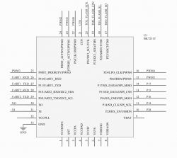
- BK7231N/T UART pads (VDD, GND, RX, TX) share the same locations on these boards [Elektroda, p.kaczmarek2, #20538978; #20538840].
- The tiny 3.3V LDO on many USB‑UART adapters can be too weak for Wi‑Fi flashing [Elektroda, p.kaczmarek2, post #20538948]
- AMS1117‑3.3V regulator is typically rated up to 800 mA; feed it with 5V, take 3.3V from its output [“AMS1117 Datasheet”].
- USB 2.0 ports can supply up to 500 mA at 5V, enough to feed the board’s AMS1117 input during flashing [“USB 2.0 Specification”].
- Proven tools: BK7231 GUI Flash Tool and hid_download_py; both linked by maintainers [Elektroda, p.kaczmarek2, #20538885; “BK7231 GUI Flash Tool”; “hid_download_py”].
How do I wire RX, TX, GND, and VDD on a BK7231N smart switch?
Match the board’s pads to UART: device RX to adapter TX, device TX to adapter RX, GND to GND, and VDD as 3.3V. The referenced WBP‑1G thread shows marked pads for similar boards. BK7231N and T share the same pad locations for these signals [Elektroda, p.kaczmarek2, #20538840; #20538978].
Why won’t my USB‑to‑TTL adapter’s 3.3V pin power the module reliably?
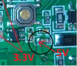
Its small LDO may not supply enough current for a Wi‑Fi SoC during flashing, causing resets or failures. As the maintainer noted, "3.3V from that tiny LDO ... may get flashing issues" [Elektroda, p.kaczmarek2, post #20538948] Use the device’s AMS1117‑3.3V regulator instead [“AMS1117 Datasheet”].
How should I power the board safely while flashing?
Feed 5V into the on‑board AMS1117‑3.3V regulator input, and keep grounds common with your USB‑UART adapter. Do not feed 5V into the 3.3V VDD pad. This method was explicitly recommended by the maintainer [Elektroda, p.kaczmarek2, post #20538948] USB 2.0 can provide up to 500 mA at 5V [“USB 2.0 Specification”].
Is BK7231N pinout the same as BK7231T for UART pads?
Yes. For these mini switch boards, RX, TX, GND, and VDD are in the same places for N and T variants [Elektroda, p.kaczmarek2, post #20538978]
CloudCutter didn’t work for me. What’s the best alternative?
Use a wired UART flash. In this thread, CloudCutter failed, but GUIFlashTool succeeded after soldering and correct wiring [Elektroda, giovannij600, #20538617; #20539031]. You can also use hid_download_py, which the project maintains [Elektroda, p.kaczmarek2, #20538885; “hid_download_py”].
Which flashing tools are recommended for BK7231N?
BK7231 GUI Flash Tool (with a step‑by‑step video) and hid_download_py are the recommended tools. Both were linked by the project maintainer in this thread [Elektroda, p.kaczmarek2, #20538885; “BK7231 GUI Flash Tool”; “hid_download_py”].
How do I enter bootloader mode (CEN) on BK7231N?
Use the CEN/RESET pin to cycle the chip into flashing mode per tool instructions. In this case, the user wired CEN for flashing and succeeded. Follow the GUIFlashTool or hid_download_py readme for the exact sequence [Elektroda, giovannij600, #20539031; “BK7231 GUI Flash Tool”; “hid_download_py”].
Do I cross RX and TX when connecting to the USB‑TTL adapter?
Yes. Connect device RX to adapter TX, and device TX to adapter RX, with a shared GND. The user proposed this mapping and the maintainer confirmed the wiring looked correct [Elektroda, giovannij600, #20539031; p.kaczmarek2, #20540011].
What are the exact steps to flash this BK7231N mini switch?
- Identify and solder to RX, TX, GND, and 3.3V/VDD pads shown in the related WBP‑1G post [Elektroda, p.kaczmarek2, post #20538840]
- Wire RX↔TX and GND, and power the board by feeding 5V to the AMS1117 input as advised [Elektroda, p.kaczmarek2, post #20538948]
- Use BK7231 GUIFlashTool or hid_download_py and follow its prompts to enter flashing mode via CEN, then write firmware [Elektroda, p.kaczmarek2, #20538885; “BK7231 GUI Flash Tool”; “hid_download_py”].
What firmware did people use after flashing?
OpenBK (OpenBeken) was successfully flashed in this case. The user confirmed flashing the latest OpenBK build after wiring and using GUIFlashTool [Elektroda, giovannij600, #20539031; #20540088].
Can I back up the original firmware before writing OpenBK?
Yes. Project maintainers encourage keeping a backup, and asked for it here after a successful flash. Use your chosen tool’s read/backup option before erasing or writing [Elektroda, p.kaczmarek2, #20540011; “BK7231 GUI Flash Tool”].
My board photos are too low‑res to find pads. What should I do?
Use a clearer reference image of the same board family. The maintainer linked a WBP‑1G thread showing pad locations. Better photos or a microscope help confirm RX, TX, VDD, and GND markings [Elektroda, p.kaczmarek2, post #20538840]
What common mistakes or edge cases should I watch out for?
- Powering from the USB‑UART’s 3.3V LDO can cause flashing failures. Use the board’s AMS1117 input with 5V instead [Elektroda, p.kaczmarek2, post #20538948]
- CloudCutter can fail on some generics; wired UART is a reliable fallback [Elektroda, giovannij600, post #20538617]
- Do not connect 5V to the 3.3V VDD pad; feed 5V only into the AMS1117 input [Elektroda, p.kaczmarek2, #20538948; “AMS1117 Datasheet”].
What about UART baud rate and serial settings?
Use the defaults provided by the flashing tool. BK7231 GUIFlashTool and hid_download_py handle the connection parameters as part of their workflows. Follow each tool’s readme or video guide [“BK7231 GUI Flash Tool”; “hid_download_py”; Elektroda, p.kaczmarek2, #20538885].
Which similar board guide can I follow for pad locations?
Refer to the WBP‑1G mini switch guide linked by the maintainer. It shows pad markings and configuration for a BK7231N + BL0942 design similar to this generic switch [Elektroda, p.kaczmarek2, post #20538840]