Note: This is a repost from my blog: https://andrewferguson.net/2022/08/23/feit-shop-4-ho-cct-ag-teardown/
The SHOP/4/HO/CCT/AG shop light is a 10,000 lumen light with tunable white light (3000K – 6500K) with a NEMA 5-15P connector that plugs into a standard 3-prong outlet.
It can be found in the US on Amazon and in retailers such as Costco for about $60 (as of the time of publishing). It’s an interesting design (in my opinion) because it’s a smart light that supports on/off, dimming, and CCT color. But at the flip of a switch you can use it just like a standard, dumb LED light.
Lights
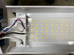
The light module contains 6 rows of LEDs (84 LEDs/row), each row alternating between cold and warm, for a total of 504 LEDs.
Major Integrated Circuits
In addition to your usual collection of resistors, capacitors, and diodes, there’s three inductors which I couldn’t figure out P/N information for. I think there’s also a thermistor or fuse of some kind (magenta circled item on top side of of PCB). I’ve highlighted the major ICs below and provided some information based on what I could find:
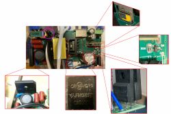
Top side
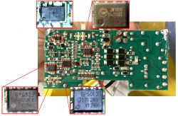
Bottom side
WB2L (BK7231T chip)
Manufacturer: Tuya
P/N: WB2L (BK7231T chip)
Function: Low-power embedded Wi-Fi and Bluetooth LE module. The chip is on a daughter board which is solder to the main board perpendicularly through a thru hole. There’s a switch that overrides the WB2L (and removes power from it!) and sets the light to cool white (not cold) color.
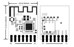
For this light, here’s what my probing found:
* PWM1: 0% duty cycle is full Cold and 100% duty cycle is full Warm
* PWM2: 0% duty cycle is off and 100% duty cycle is full brightness.
* PWM5: Unknown if this is an input or an output. With the stock Feit firmware:
** Logic 0: when the light is on
** Logic 1: when the light is off
BP2525
Manufacturer: Bright Power Semiconductor
P/N: BP2525
Function: Non-isolated step-down type AC/DC Constant Voltage chip…power for the LEDs that is then current controlled by the BP2929 (for color temperature) and BP5012 (for dimming).
Datasheet
BP5929
Manufacturer: Bright Power Semiconductor
P/N: BP5929
Function: Dual-channel PWM color matching chip1
This is an interesting chip, and I’m not quite sure why they’re using it. Normally, the microcontroller would output two PWM signals: one for Cool White and one for Warm White, and they would each drive a MOSFET and then dimming is handled algorithmically by the microcontroller. This chips seems to offload that functionality (sort of; this chip doesn’t actually handle dimming itself, but rather in combination with a separate current control method — which I believe is the BP5012 in this design), but I’m not sure why…the microcontroller can do all of this easily. My one thought is that maybe this method reduces flicker because it’s relies of constant voltage instead of using PWM to vary the voltage.
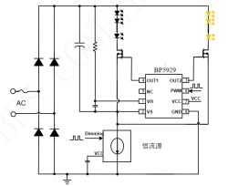
Google translation of datasheet…so may not be exactly accurate
Datasheet
BP5012
Manufacturer: Bright Power Semiconductor
P/N: BP5012 or BP501 (maybe)
Function: PWM dimming interface converter (probably)
I couldn’t find a datasheet for BP5012 or BP501. There is a BP5011 though, which is a 2 channel PWM dimming controller. So I suspect it’s related to that.
Datasheet
JW1606
Manufacturer: Joulwatt
P/N: JW1602
Function: Non-isolated switching regulator with dimming
The package is marked JW1606, but JW1606 doesn’t exist. I’m assuming this is related to the JW1602, which I was able to find a datasheet for.
The JW1602 has dimming function, so I’m not sure why the duplicate functionality with the BP5012. The BP2525 is also a non-isolated switching regulator as well. So my theory is that there’s two completely separate control circuits on the PCB, one to provide variable control of color temperature and intensity when the microcontroller is active and another circuit that provides fixed color temperature (probably just 50/50) and a fixed dimming level (set by a voltage divider).
Datasheet
GBU 4J
Manufacturer: onSemi
P/N: GBU4J
Function: Bridge Rectifier. Probably for input to both of the non-isolated switching regulators (BP2525 and JW1606).
Datasheet
CRJF380N65G2
Manufacturer: CR Micro
P/N: CRJF380N65G2
Function: SJ-MOS N-MOSFET. I think this is used only when the unit is in “dumb” mode and provides the variable current control for all 504 LEDs.
Datasheet
SVF4N65F
Manufacturer: Silan Microelectronics
P/N: SVF4N65F
Function: N-CHANNEL MOSFET. There’s two of these that are directly connected to the LEDs themselves, one for each color temperature. These are probably driven by the BP5929 to control the current for each set of LEDs.
Datasheet
7002
Manufacturer: CT Micro
P/N: CT2N7002E-R3
Function: N-Channel Enhancement MOSFET. I think this is somehow related to the mysterious function of PWM5.
Datasheet
Disassembly
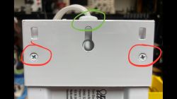
Remove screws and cable clamp
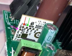
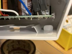
Slide out PCB
BK7231T is pretty straight forward:
1. Remove two screws from cord side (red circles)
2. Remove cord clamp (green circle)
3. Slide the the PCB out from its slot
Note: this might require scrapping some of the potting compound used to the secure the PCB into the slot. Pushing gently from the end using the switch usually pops it out
Flashing
I flashed the unit with OpenBK7231T/OpenBeken, which now supports this light. I followed the UART instructions, which requires using https://github.com/OpenBekenIOT/hid_download_py.
I used a USB to Serial USB to TTL CH340G to program the chip. Once the PCB is removed, make the following connections:
* Connect computer TX to U1_RXD (Top side: red arrow)
* Connect computer RX to U1_TXD (Top side: green arrow)
* Connect a wire to the RST (Top side: magenta arrow), when you’re ready to program you’ll briefly connecting this to ground to reset the chip.
* Connect 3.3 volts to 3V3 (Bottom side: red arrow)
* Connect ground to GND (Bottom side: black arrow)
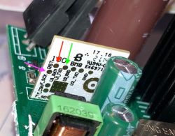
Top Side: Connect TX, RX, and Reset
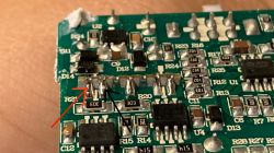
Bottom Side: Connect 3.3V and Ground
Outstanding Questions
* What does PWM5 do?
* Does power get cut to WB2L when switch is activated?
* What are the other chips?
* What chip is used for LED control?
The SHOP/4/HO/CCT/AG shop light is a 10,000 lumen light with tunable white light (3000K – 6500K) with a NEMA 5-15P connector that plugs into a standard 3-prong outlet.
It can be found in the US on Amazon and in retailers such as Costco for about $60 (as of the time of publishing). It’s an interesting design (in my opinion) because it’s a smart light that supports on/off, dimming, and CCT color. But at the flip of a switch you can use it just like a standard, dumb LED light.
Lights
The light module contains 6 rows of LEDs (84 LEDs/row), each row alternating between cold and warm, for a total of 504 LEDs.

Major Integrated Circuits
In addition to your usual collection of resistors, capacitors, and diodes, there’s three inductors which I couldn’t figure out P/N information for. I think there’s also a thermistor or fuse of some kind (magenta circled item on top side of of PCB). I’ve highlighted the major ICs below and provided some information based on what I could find:

Top side

Bottom side
WB2L (BK7231T chip)
Manufacturer: Tuya
P/N: WB2L (BK7231T chip)
Function: Low-power embedded Wi-Fi and Bluetooth LE module. The chip is on a daughter board which is solder to the main board perpendicularly through a thru hole. There’s a switch that overrides the WB2L (and removes power from it!) and sets the light to cool white (not cold) color.

| Pin No. | Symbol | I/O type | BK7231T Function | Use |
| 1 | PWM2 | I/O | Hardware PWM pin; P8/BT_ACTIVE/PWM2 (Pin24) | Dimmer |
| 2 | PWM1 | I/O | Hardware PWM pin; P7/WIFI_ACTIVE/PWM1 (Pin23) | Color Temperature |
| 3 | PWM0 | I/O | Hardware PWM pin; P6/CLK13M/PWM0 (Pin22) | No Connect |
| 4 | PWM5 | I/O | Hardware PWM pin; P26/IRDA/PWM5 (Pin15) | Unknown |
| 5 | PWM4 | I/O | Hardware PWM pin; P24/LPO_CLK/PWM4 (Pin16) | No Connect |
| 6 | GND | P | Ground pin | GND |
| 7 | 3V3 | P | Power supply pin (3.3 V) | 3.3 V |
For this light, here’s what my probing found:
* PWM1: 0% duty cycle is full Cold and 100% duty cycle is full Warm
* PWM2: 0% duty cycle is off and 100% duty cycle is full brightness.
* PWM5: Unknown if this is an input or an output. With the stock Feit firmware:
** Logic 0: when the light is on
** Logic 1: when the light is off
BP2525
Manufacturer: Bright Power Semiconductor
P/N: BP2525
Function: Non-isolated step-down type AC/DC Constant Voltage chip…power for the LEDs that is then current controlled by the BP2929 (for color temperature) and BP5012 (for dimming).
Datasheet
BP5929
Manufacturer: Bright Power Semiconductor
P/N: BP5929
Function: Dual-channel PWM color matching chip1
This is an interesting chip, and I’m not quite sure why they’re using it. Normally, the microcontroller would output two PWM signals: one for Cool White and one for Warm White, and they would each drive a MOSFET and then dimming is handled algorithmically by the microcontroller. This chips seems to offload that functionality (sort of; this chip doesn’t actually handle dimming itself, but rather in combination with a separate current control method — which I believe is the BP5012 in this design), but I’m not sure why…the microcontroller can do all of this easily. My one thought is that maybe this method reduces flicker because it’s relies of constant voltage instead of using PWM to vary the voltage.

| Pin Number | Name | Description |
| 1 | VH | High-voltage side power supply terminal |
| 2 | VS | High pressure side floating |
| 3 | OUT2 | Output GATE signal 2 |
| 4 | OUT1 | Output GATE signal 1 |
| 5 | NC | Not Connected |
| 6 | PWM | PWM Signal Input |
| 7 | VCC | Low voltage power supply |
| 8 | GND | Ground |
Google translation of datasheet…so may not be exactly accurate
Datasheet
BP5012
Manufacturer: Bright Power Semiconductor
P/N: BP5012 or BP501 (maybe)
Function: PWM dimming interface converter (probably)
I couldn’t find a datasheet for BP5012 or BP501. There is a BP5011 though, which is a 2 channel PWM dimming controller. So I suspect it’s related to that.
Datasheet
JW1606
Manufacturer: Joulwatt
P/N: JW1602
Function: Non-isolated switching regulator with dimming
The package is marked JW1606, but JW1606 doesn’t exist. I’m assuming this is related to the JW1602, which I was able to find a datasheet for.
The JW1602 has dimming function, so I’m not sure why the duplicate functionality with the BP5012. The BP2525 is also a non-isolated switching regulator as well. So my theory is that there’s two completely separate control circuits on the PCB, one to provide variable control of color temperature and intensity when the microcontroller is active and another circuit that provides fixed color temperature (probably just 50/50) and a fixed dimming level (set by a voltage divider).
Datasheet
GBU 4J
Manufacturer: onSemi
P/N: GBU4J
Function: Bridge Rectifier. Probably for input to both of the non-isolated switching regulators (BP2525 and JW1606).
Datasheet
CRJF380N65G2
Manufacturer: CR Micro
P/N: CRJF380N65G2
Function: SJ-MOS N-MOSFET. I think this is used only when the unit is in “dumb” mode and provides the variable current control for all 504 LEDs.
Datasheet
SVF4N65F
Manufacturer: Silan Microelectronics
P/N: SVF4N65F
Function: N-CHANNEL MOSFET. There’s two of these that are directly connected to the LEDs themselves, one for each color temperature. These are probably driven by the BP5929 to control the current for each set of LEDs.
Datasheet
7002
Manufacturer: CT Micro
P/N: CT2N7002E-R3
Function: N-Channel Enhancement MOSFET. I think this is somehow related to the mysterious function of PWM5.
Datasheet
Disassembly

Remove screws and cable clamp


Slide out PCB
BK7231T is pretty straight forward:
1. Remove two screws from cord side (red circles)
2. Remove cord clamp (green circle)
3. Slide the the PCB out from its slot
Note: this might require scrapping some of the potting compound used to the secure the PCB into the slot. Pushing gently from the end using the switch usually pops it out
Flashing
I flashed the unit with OpenBK7231T/OpenBeken, which now supports this light. I followed the UART instructions, which requires using https://github.com/OpenBekenIOT/hid_download_py.
I used a USB to Serial USB to TTL CH340G to program the chip. Once the PCB is removed, make the following connections:
* Connect computer TX to U1_RXD (Top side: red arrow)
* Connect computer RX to U1_TXD (Top side: green arrow)
* Connect a wire to the RST (Top side: magenta arrow), when you’re ready to program you’ll briefly connecting this to ground to reset the chip.
* Connect 3.3 volts to 3V3 (Bottom side: red arrow)
* Connect ground to GND (Bottom side: black arrow)

Top Side: Connect TX, RX, and Reset

Bottom Side: Connect 3.3V and Ground
Outstanding Questions
* What does PWM5 do?
* Does power get cut to WB2L when switch is activated?
* What are the other chips?
* What chip is used for LED control?
Cool? Ranking DIY


