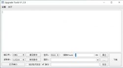
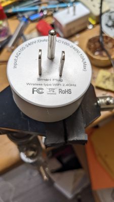
This is a teardown of an unbranded wifi switch named SmartPlug. The printed manual referred to Smart Life app.
The appearance is quite generic with a single button on one side. There is a blue LED around the button.
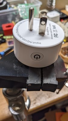
I was able to safely open using using a sharp spudger. The electronics are recessed so spudger has quite less change of damaging anything. Desoldering the power connections takes patient but I was able to do just using a desoldering wick.
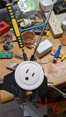
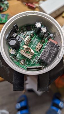
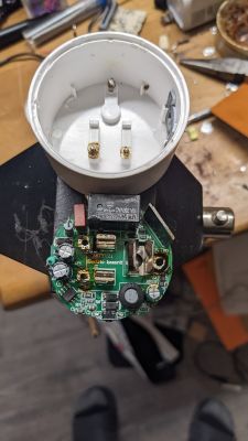
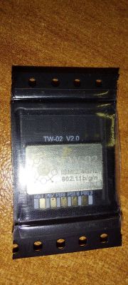
And here is the cleaned up board and the chip.
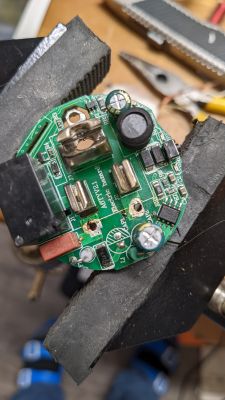
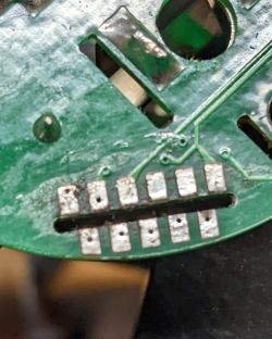
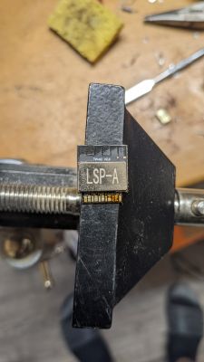
The module had power and serial connection cleared marked and serial connection showed this.
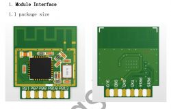
So LSP-A was actually a W600 TW-02 module.
W600 - https://www.winnermicro.com/en/html/1/156/158...%20Wi,industrial%20and%20other%20IoT%20fields.
There is also a FCC filing about TW-02 - https://fccid.io/2ASQV-TW-03/User-Manual/User-manual-4210975.pdf

Examination of the board showed that there was actually a red and a blue LED; red was tied to the relay.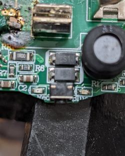
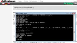
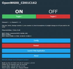
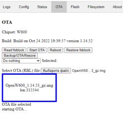
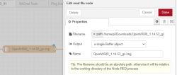
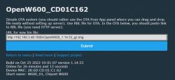
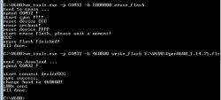
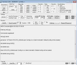
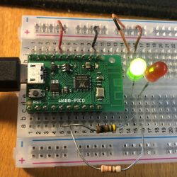
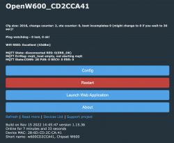
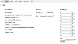
Later I was able to adjustOpenBK7231T app to compile the W600 SDK (originally obtained from https://github.com/w600/sdk). The W600 build is now part of OpenBK7231T's standard build.
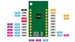
And here are the actual connections:
Side-A
* 3.3V
* Gnd
* PA5 connected to switch pulled high
* PA4 - No connection
* PB16 - No connection
* PB15 - relay tied to red LED
Side-B
* PB13 - No connection
* PB18 - No connection
* PB8 - blue LED
* PB7 - No connection
* Reset - No connection
The module seems to run a bit warm and took around 80mA in stock condition before custom firmware. The FCC filing mentioned that it can consume up to 230 mA so this was well within range.
The appearance is quite generic with a single button on one side. There is a blue LED around the button.


I was able to safely open using using a sharp spudger. The electronics are recessed so spudger has quite less change of damaging anything. Desoldering the power connections takes patient but I was able to do just using a desoldering wick.


And here is the cleaned up board and the chip.


The module had power and serial connection cleared marked and serial connection showed this.
<TUYA IOT SDK V:2.0.0 BS:30.01_PT:2.2_LAN:3.3_CAD:1.0.1_CD:1.0.0 >
[FW]: TC0025_TW02_PLUG_L1_P0 | [HW]: TW-02 V2.0 | [SW]: V1.4.0 (Nov 18 2019 08:48:17) | [PID]: nqvhejakb112obkn
[01-01 00:00:00 TUYA Notice][hw_table.c:532] wifi status is :0
[01-01 00:00:00 TUYA Notice][wifi_hwl.c:1316] <LF> old mode is 4 <LF>
[01-01 00:00:04 TUYA Notice][tuya_main.c:143] wf_assign_ap_scan failed(-606)
[01-01 00:00:04 TUYA Notice][gw_intf.c:2270] gw_cntl.gw_wsm.stat:1
[01-01 00:00:04 TUYA Info][wifi_hwl.c:1261] Low Power Mode
[01-01 00:00:05 TUYA Notice][hw_table.c:532] wifi status is :0
[01-01 00:00:14 TUYA Notice][tuya_device.c:694] free_mem_size:89880
So LSP-A was actually a W600 TW-02 module.
W600 - https://www.winnermicro.com/en/html/1/156/158...%20Wi,industrial%20and%20other%20IoT%20fields.
There is also a FCC filing about TW-02 - https://fccid.io/2ASQV-TW-03/User-Manual/User-manual-4210975.pdf


Examination of the board showed that there was actually a red and a blue LED; red was tied to the relay.

Later I was able to adjustOpenBK7231T app to compile the W600 SDK (originally obtained from https://github.com/w600/sdk). The W600 build is now part of OpenBK7231T's standard build.
And here are the actual connections:
Side-A
* 3.3V
* Gnd
* PA5 connected to switch pulled high
* PA4 - No connection
* PB16 - No connection
* PB15 - relay tied to red LED
Side-B
* PB13 - No connection
* PB18 - No connection
* PB8 - blue LED
* PB7 - No connection
* Reset - No connection
The module seems to run a bit warm and took around 80mA in stock condition before custom firmware. The FCC filing mentioned that it can consume up to 230 mA so this was well within range.
Cool? Ranking DIY


